Testing for Square of our Laguna Swift 5 × 10 CNC

Our Laguna Swift CNC router with its 5 × 10-foot bed and RichAuto B58 controller has two Y-axis motors, one on each side of the gantry, but it does not have independent left and right Y-axis homing switches.

I was concerned that the gantry might be canted slightly, causing the machine to produce parallelograms instead of truly square rectangles. I performed the following test by putting corner squares of foil tape and cutting into them.
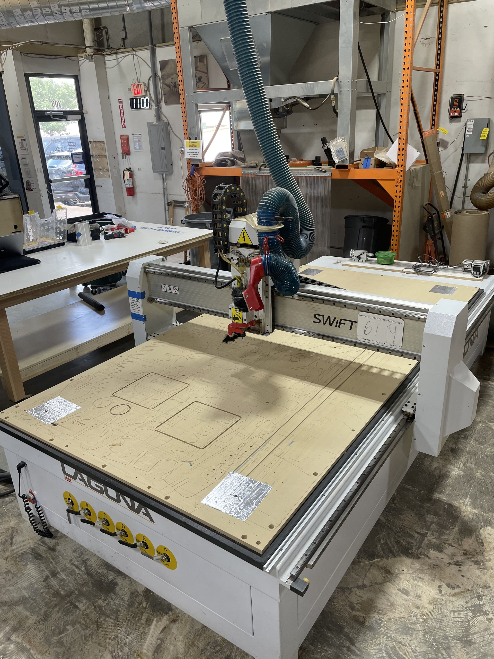
Test setup

I used:

  • A 15° V-bit
  • A marking depth of 0.020 inch
  • A safe Z height of 0.250 inch
  • Four shallow dimples marking the corners of a large rectangle
  • Work zero set on top of the material at the lower-left test point

The test rectangle measured:

  • X: 45 inches
  • Y: 108 inches
  • Expected diagonal: exactly 117 inches

This is a scaled 5–12–13 right triangle:

45² + 108² = 117²

The rectangle was centered on the nominal 60 × 120-inch bed. That placed the lower-left work origin:

  • 7.5 inches inside the usable X edge
  • 6 inches inside the usable Y edge

The G-code marked these four positions:

Lower left:   X0,   Y0
Lower right:  X45,  Y0
Upper right:  X45,  Y108
Upper left:   X0,   Y108

Diagonal measurements

I measured from the centers of the V-bit dimples and obtained:

Diagonal Measurement
Lower-left to upper-right 117.125 inches
Lower-right to upper-left 116.875 inches
Difference 0.250 inch
Average 117.000 inches

The average of the two diagonals is exactly the intended 117 inches, but one diagonal is 0.125 inch long while the other is 0.125 inch short.

This appears to indicate a consistent angular or squareness error rather than a general X- or Y-axis scale-calibration problem.

Repeatability test

I then ran a second program that revisited all four dimples three times. It approached the corners from different directions to help reveal:

  • Lost steps
  • Drive slippage
  • Backlash
  • Movement between the two Y motors
  • Poor return-to-position repeatability

Every pass entered the existing dimples in exactly the same position. I could not see any enlargement, offset or additional marks.

This suggests that:

  • Both Y motors remain synchronized while the machine is energized.
  • There is no obvious lost-step or drive-slippage problem.
  • The machine has good short-term positional repeatability.
  • The out-of-square condition appears stable and repeatable.

Estimated gantry error

Based on the two diagonal measurements, the axes appear to be out of perpendicular by approximately:

0.172 degrees

For a 45-inch-wide gantry, the calculated relative Y displacement between its two ends is approximately:

0.135 inch

Because the lower-left-to-upper-right diagonal is the longer one, my current interpretation is that the right side of the gantry is approximately 0.135 inch farther in the positive Y direction than the left side.

The theoretical correction would therefore be one of the following:

  • Move the right side approximately 0.135 inch toward negative Y, or
  • Move the left side approximately 0.135 inch toward positive Y

Only one side would be moved by that amount—not both sides by 0.135 inch.

I would treat 0.135 inch as an initial calculated correction, followed by another diagonal test, rather than assuming that one adjustment will be perfect.
1 Like

Thank you for checking! What prompted the test? 1/4" is quite off. I haven’t used the Laguna in a few months, but cut quite a few cabinet carcass and slab door/drawer fronts over the course of two months and didn’t notice any panels being significantly out of square. Most of my cuts were relatively short along the Y-axis so the error might have been within tolerance for ordinary cabinets.

So who would be responsible for adjusting the gantry?

When we used it on Thursday, I noticed that when the machine is homed, the right side of the gantry was more than a 1/4 in away from the stop on that side.

I am wondering if we try Eric’s procedure would it help. Basically pull that right side gantry to the stop while the machine is homed.

If that does help, maybe there is a way we can shim the gantry so it homes more accurately.

I had significant error on my last large panel cut as discussed in a previous post. I have not been back to test pulling the gantry to ensure fully bumping the stops, but will have to check prior to my next panel as it is a large format two-sided cut. If not square, then I cannot proceed with that cut.

@bwatt Did you pull the gantry as discussed in earlier posts to ensure seated on the stops prior to turning on machine and performing your test above?

No adjustment of the large CNC was done other than homing it. I wanted to treat the unit as-is.

I generated the following individual files for testing squareness:

I used 00_AIR_TEST.mmg to figure out where to position the aluminum tape patches. Then I ran 01_CORNER_DIMPLES.mmg to create dimples and get the measurements. Finally I ran 03_REPEAT_DIMPLES.mmg to verify that the dimples repeated at the same location when moving clockwise and counter-clockwise from dimple to dimple. I never used 02_RECTANGLE_OUTLINE.

When they designed this machine they saved about eight dollars by eliminating a sensor. As soon as you turn the machine off it’s like leaving your car in neutral instead of park. The first time someone rests some wood against the gantry or even from the force of the vacuum hose, it will move slightly more on one side than the other and be out of square. Since they skipped the sensor, the machine doesn’t know if the gantry is slightly crooked.

If you just want to get a square cut, then every time you show up to use the machine, jog it in Y-, power off the steppers, then grab the gantry from the back and pull it against the rubber stops. Then power on the switch and wait one second till you feel the steppers turn on. (FYI this requires some moderate leaning to reach the switch and if the floor is slippery then you could potentially fall. Don’t fall.)

The machine is now mostly square. (You can verify it and post the results here.)

When you show up to use the machine, you already have to do a lot of stuff like: Check the dust collector, check to make sure the area is clear around the gantry, make sure the water pump is plugged in. So this is one more thing which you do.

If you believe that a CNC router ought to be square just as a matter of principle, there are technical fixes. Best case is RichAuto supports the dual sensor homing, we already have the documentation, and Laguna Co., Inc. will send you some sensor brackets if you email them. In this case it takes two hours to run some sensor wires and the machine will square itself when you home it. More realistically it’ll probably take ten hours of CAD work and twenty hours of fabricating and setup, and you’ll have to make the brackets yourself in the metal shop, and maybe the control doesn’t even support it, or maybe the documentation is terrible or nonexistent.

tl;dr power it off and power it on again (whilst pulling the gantry against the stops)

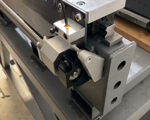
P.S. Here is a Y axis endstop setup I designed for my own CNC router. The orange light with the wire is the inductive sensor and there is one on each side. The sensors faces downward to avoid false triggers due to falling chips.

I tried this and you can’t really get the gantry all the way to the stop, at least not without a ton of force. I don’t think it’s reasonable to have each CNC user do this procedure, particularly with the force it requires. Barring any dual sensor option, it seems like we should be able to adjust the gantry so its rest position is more square, so that when it does home, it also more likely to be square.

If you loosened the Y carriage screws and re-tightened them then it might help it not spring back.

It would take more than another sensor. The controller doesn’t have a second output for a two-motor linked gantry axis. When it reads one sensor trip before the other, there’s still no way to correct it.

There’s no good fix for this. It shouldn’t be able to go out of squaring during use, but whatever relative difference there is while it’s first powered up is locked in. One of many liabilities of going with a RichAuto.

That is not consistent from run to run. So, the more accurate test is to power it down. push on one side of the gantry but not the other, then power up and test to see how much it’s capable of going out of square.

All you need is a single diagonal, BTW. Assuming the axes are tracking correctly- and it would be a pretty big deal if there were any issue there- the diagonal across 45, 108 must be 117. You measured the fundamental sync error correctly with one measurement, the second measurement is somewhat redundant.

I tried the pull-gantry-method ahead of a planned square test last night as well. Like @atwatsoniii pulling from center, I can only get right upright to ~1/4” of its stop. I can pull fully to the stop if pulling closer to the right, but then cannot reach the console to re-energize the system. Something is off and I do not think in its current condition that the pull-gantry-method is the best solution. Next time I can try pulling while someone else energizes to see if it retains position and run square test, but even if it works, that is not practical for everyday use. For a 5’x10’ CNC, this skew is meaningful and will prevent users from performing large panel work, especially 2-sided, where the skew will appear doubled.

Are the drives fully independent when off or could it have skipped a tooth or two during a crash at some point and retain a skew?

I am happy to come in and help with a fix or call Laguna for advice. @jamesfreeman Any thought on this?

I would be happy to assist squaring the Laguna Swift and run the above GCODE to recheck it. From Google search of “squaring laguna swift 5 x 10”:

Mechanical Squaring Procedure

Once you know which side of the gantry sits too far forward or backward, you must manually align the legs: [1, 2]

  1. Power Down: Turn off the CNC completely to remove power from the dual Y-axis stepper/servo motors. This un-locks them so the two sides can move independently. [1]
  2. Loosen Mounts: Locate the mounting plates where the gantry connects to the bearing sleds on both the left and right rails. Slightly loosen the bolts (typically 4 to 8 per side) securing the gantry uprights to the linear bearing blocks. Leave them finger-tight so they don’t shift freely but allow for controlled adjustment. [1, 2, 3]
  3. Nudge the Gantry: Use a clamp, a block, or gently tap the gantry leg on the lagging side forward (or the advanced side backward) using a flat crowbar or soft mallet. [1, 2]
  4. Re-Measure and Lock: Continually re-check your physical tape measurements across the frame until the two diagonals match perfectly. Tighten the bolts in an alternating, crisscross pattern to secure the gantry back to the rail sleds. [1, 2, 3]
  5. Verify the Fix: Power the machine back up, execute a hard home cycle, and re-run your 4-corner test pattern to ensure the cut marks match perfectly. [1, 2]

Preventing Future Racking

To save yourself from doing manual alignment every time the machine power cycles, use a Hard Limit Reference System: [1]

  • With the machine completely square, pull or drive the gantry slowly to the absolute maximum front (or back) end of the physical travel.
  • Fasten physical hard stops (like a block of aluminum or steel) flush against both tracks where the gantry naturally stops.
  • If the machine ever power faults or loses its relative squareness, you can turn off the machine, push both sides firmly against your physical stops, and turn it back on to restore alignment instantly. [1, 2, 3]

If this process is approved, I will come in to help as well.

My current project is on hold as the alignment is way too far off to do any large panel work, especially 2-sided large panel work. If we can get it “closer” to square on a All Axis Home, then the simple pull procedure should work from there for normal operations. Right now, it is a two person endeavor and I do not feel comfortable pulling so hard on the right upright to get it to the stop - wouldn’t want to cause a different problem…

Or perhaps we try the 2-person pull method and your squareness test first before attempting any other physical adjustments. Don’t want to solve one problem and create another.

I do think the carriage needs to be loosened to really square this time.it @jamesfreeman can chime in and f he has any objections but I would say proceed.

Might also be a good idea for one of us to contact Laguna Support explaining our issue and agree with whatever plan we decide to move forward with.

The simplest approach would be to Re-Home, loosen right hand gantry bolts, nudge back to the physical stop, re-tighten and run square test again. Could it be this simple??? That seems too simple, so it would be best to have a conversation, request an exploded parts / service diagram, and get Laguna’s agreement with our plan of attack. I could not find a parts diagram and am not in front of the CNC to see if obvious or not.

Happy to try Laguna Support, but not sure if they would need an official ASMBLY representative.

Feel free to reach out. it is something we’ve done before.

not much to these machines in reality.

So someone has loosened and realigned before? If so, then we should just proceed as discussed.

I’d like @jamesfreeman there if we do. I’ll be glad to be there to lend support and run another square test.

Yes, I have loosened and aligned before. it’s just a few hex head screws. The puck needs recalibration as well if you guys are up for that.