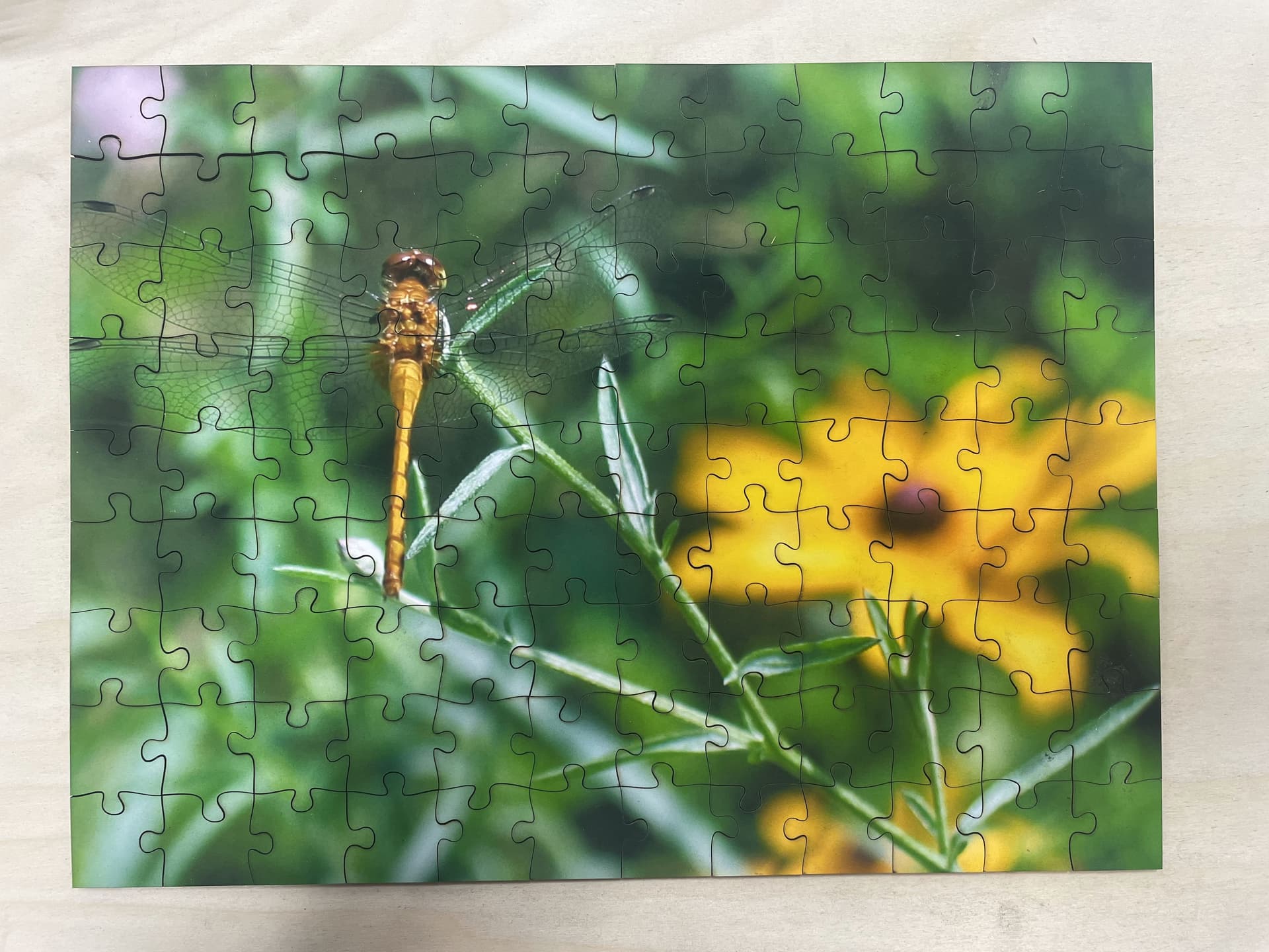
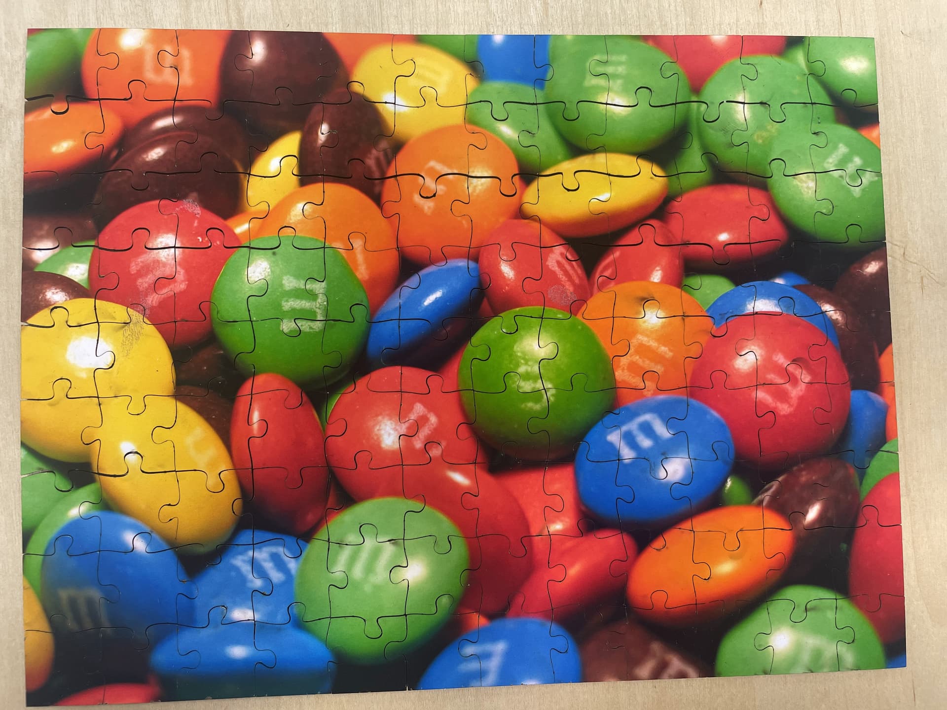
I made a simple puzzle, a prototype for something much larger and more complex. I printed two photos I shot a long time ago onto matte inkjet photo paper, then glued them onto opposite sides of chipboard, then cut that on the laser Dorian. It came out very nicely, better than I had expected.
The puzzle is 7.5" x 10", 9 pieces by 12 pieces, so each piece is about 5/6" square. The pieces do fit together a bit more loosely than I would like. That could be a kerf issue, but I suspect it’s also because the puzzle is very thin. The chipboard I could get readily in town is about half the thickness you would want for a good puzzle.
I’m thinking I will still make and try a drag knife for the CNC, just to see how they compare. Unlike the laser, the knife won’t actually remove material; any kerf will just be from compression of the materials. But I don’t know if it will cut cleanly enough. But this is a very good start and will probably suffice even if it can’t be improved.
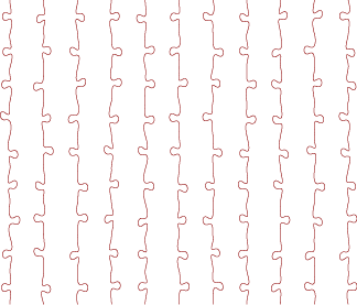
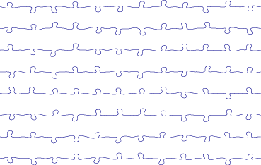
FYI, the cut out design came from here: Jigsaw puzzle generator - Free Laser Designs - Glowforge Owners Forum That program did a really great job of creating conventional looking puzzle pieces with enough randomization to make the pieces unique. And the SVG file it creates gives you all the horizontal cuts as one curve and the vertical cuts as another; it doesn’t try to cut out individual pieces, which would require sharp corners.
Impressive! Did you need to do anything in regards to stopping any soot from depositing on either side? Like taping it up or something? I’ve thought about doing a similar thing.
Is a drag knife strong enough to cut all the way through chipboard like that? maybe just with a bunch of passes…
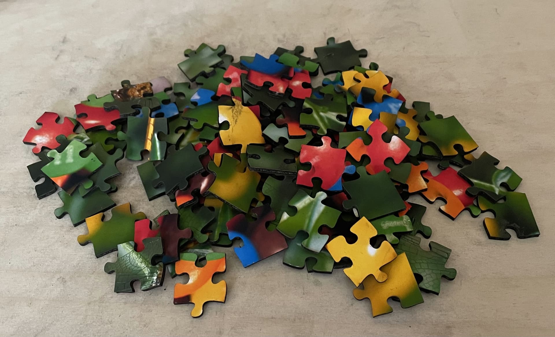
The opposite side is an issue; there was either soot deposit and/or the grid was just dirty. Plus, cutting it on the grid was a bad idea for another reason: moving it. It was immediately coming apart, so I had to half reassemble the puzzle on the spot! I will definitely place it on a piece of spoil cardboard or something the next time I try cutting one on the laser.
Having recently worked with a drag knife I think this project might prove to be a challenge. The cutting by the blade can’t maneuver beyond the cut vector because you can’t cut into the adjacent piece. Extending beyond the cut vector is the best way to get crisp corners with a drag knife. The optional pivot-in-place motion can chew up corners a bit. Also, those tab corners may be too tight a radius for drag knife motion. My experience is limited so hopefully I’m wrong.
My cautionary tale shouldn’t dissuade you from trying. You can learn a lot from 1) analyzing the tool path produced VCarve’s Drag Knife Gadget and 2) test cutting on a few pieces for analysis. In the end, you may be able to get acceptable results but maybe on thinner stock.
Please come back afterwards and educate us with what you learn.
OK, so I’ve definitely watched other videos of his, and I’d come across links to this one, but I hadn’t watched it yet. I guess my puzzle is a “100 piece puzzle”, with 108 pieces. But I have a perfect 1:1 piece size ratio; both the picture and the grid ratios are 4:3. I actually had to do an awkward crop on the “Brown Eyed Girls” picture to get it to the same ratio as the “Intruder” picture; I cut off a wing tip on the left and a petal on the right. But it was just for the test anyway.
Yeah, I’ll have to see if the drag knife turning radius can handle the tabs or not. That will depend on the size of the pieces too. But there are no sharp corners to cut via pivoting; as I mentioned above, the SVG file I use separates the vertical and horizontal cuts, as I show below. The sharp corners then arise from the separate cuts crossing.
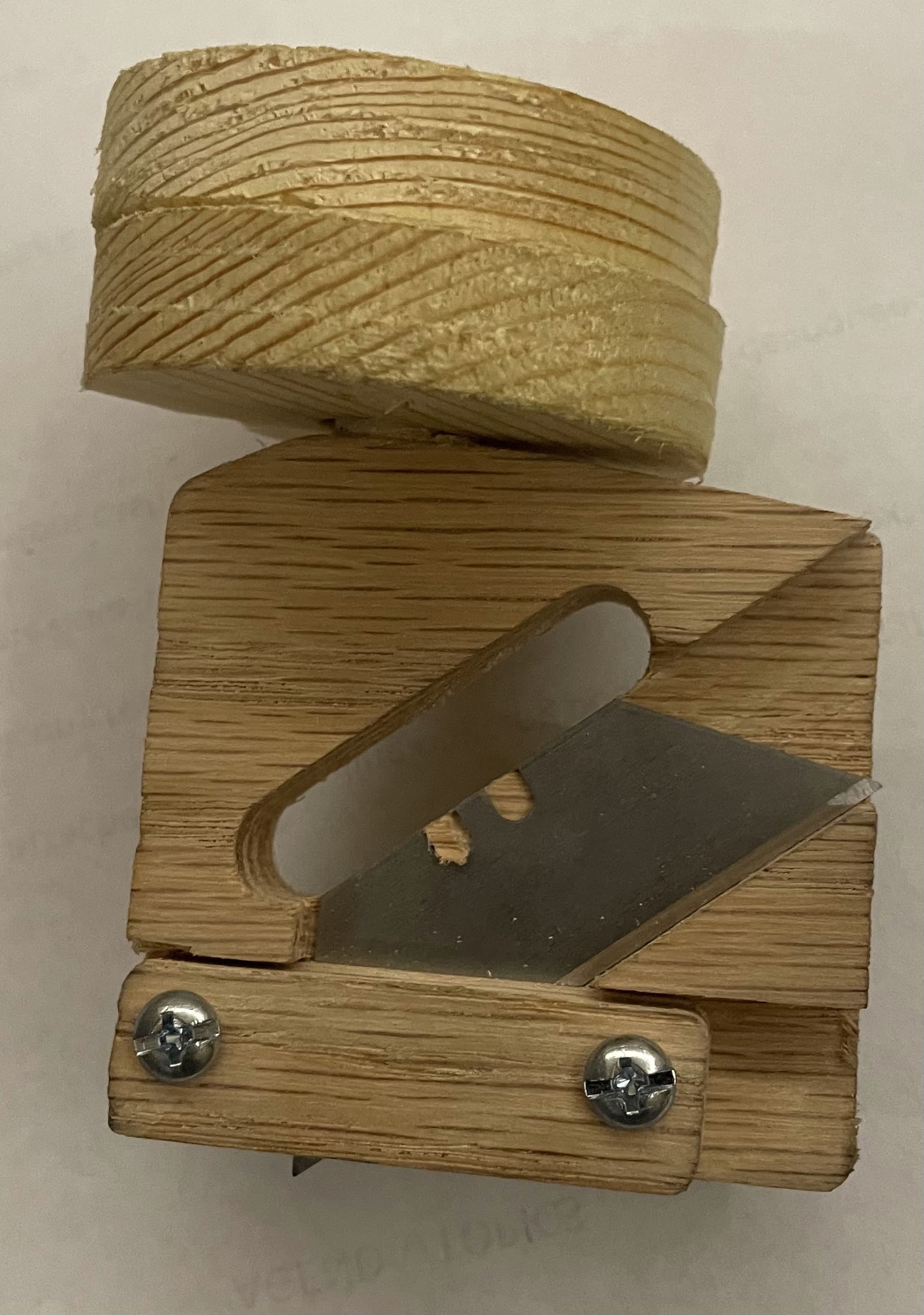
A step towards a drag knife for the CNC. More a proof of concept than a prototype at this point, as even a decent quality hardwood cracked in several places when I was assembling it. (The first attempt with cheap Home Depot white wood was even worse.) It was cut on the CNC, based off a design I found online, the aluminum precursor of the 3-D printed version that Travis posted a link to in another thread.
I’m not clear on why the design uses two bearings rather than one; my best guess is just to provide a longer length of constrained shaft for stability. Amazon sold those bearings in packs of two anyway, but I’ve been looking for ways to simplify the design.
It still needs a few tweaks, but I’m considering these options going forward:
Cut it on the CNC out of an appropriate hard plastic.
Cut it on the CNC out of aluminum. It will take a thicker block than would usually be cut on the CNC, but it should still be feasible if I pay attention to the details of spindle speed and cut rates. And I understand those issues much better with aluminum than I do with the various plastic options.
Cut it on the manual mill and lathe. This was my original intention, which is why I worked to simplify it, but no matter what, the key features are at 37.48 degrees to the horizontal. I see some possible ways to set the cuts up using a blade as a guide, but it will definitely be tricky.
Learn to use the Tormach already, which I should really do since my focus as a new steward will be the machine shop. But that takes my time, my money, and Eric’s time, all of which are in short supply right now.
(Note that 3D printing it is not a good option. I know little about doing so, so the issue of paying for and taking classes remains. And apparently the 3D-printed versions have not worked well. Depending on what plastic they used, they’ve either bent or broken.)
Aluminum is clearly the way to go, but I’ll have to think more about how.