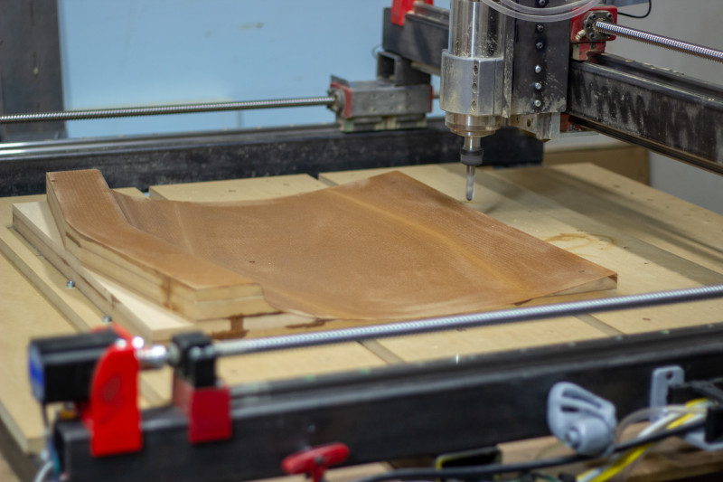
I’m interested in molding clay and it seems the quickest route might be cutting the forms in wood on a CNC router. I found a topic mentioning the Carveco Maker program which seems very capable. I was just wondering if there are others interested in doing the same or maybe someone with experience who would be willing to help jump start the process with compensation.
1 Like
This is right up @HannaKessler’s alley. She showed us using these molds in her class.
I’m happy to help you with this also, however if I do it’ll be in Fusion360 (which is free), not carveco.
I’ve got a bit of free time tomorrow and Saturday if you want to do it then!
Yes I remember. @HannaKessler is the one responsible for sending me down this latest rabbit hole lol. Btw, I loved your class Hanna.
So I made a simple mold on the table saw.
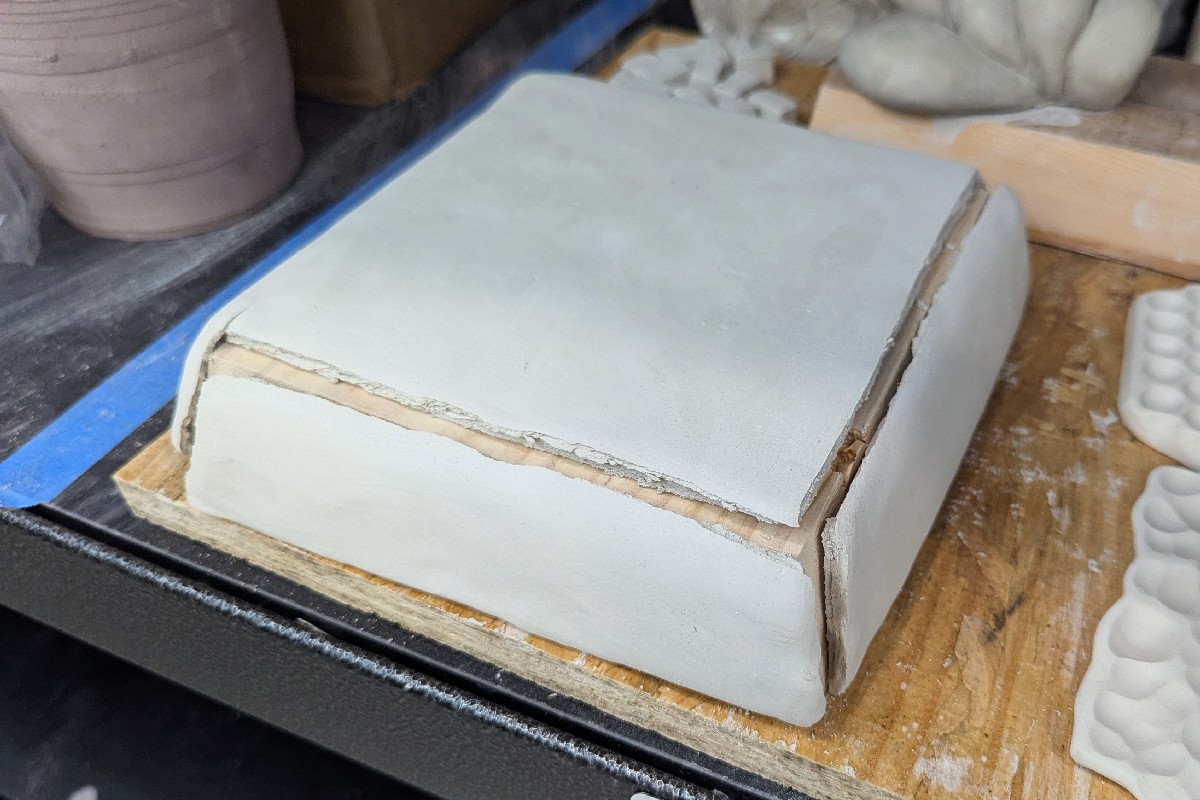
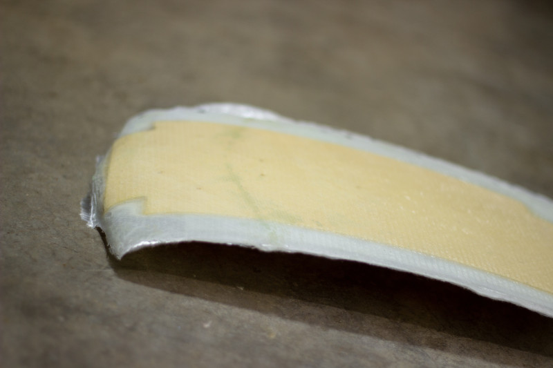
This was five pieces of clay joined at the edges and left to dry on the mold. Wow, clay shrinks a lot when it dries. So I’m not a clay guy yet. I smoothed the mold on the belt sander and used a single piece of clay for improved results.
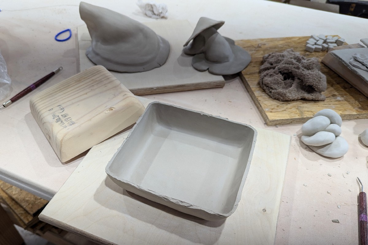
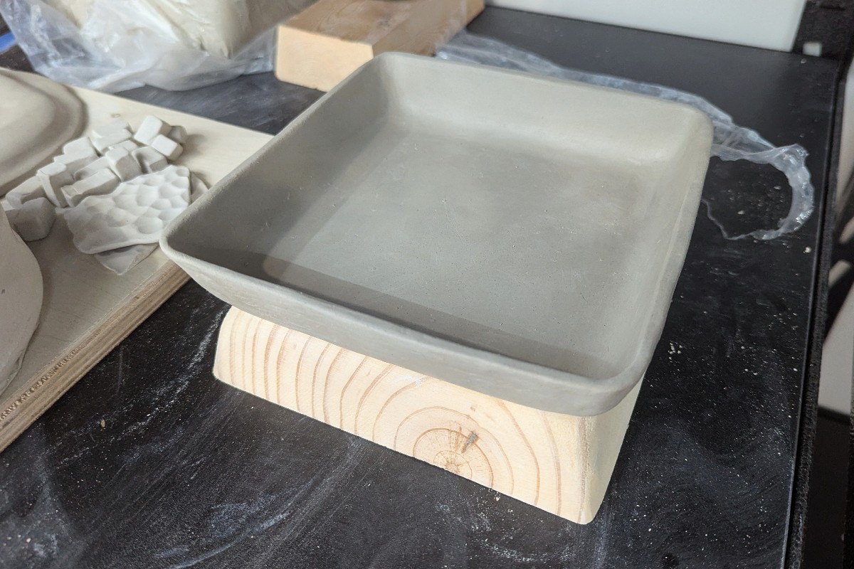
After cleaning the edges the piece held its shape and dried without the aid of the mold.
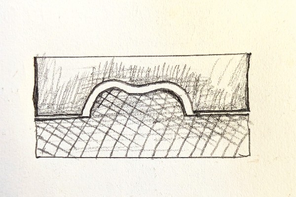
What I really want to do is create undulating complex shapes of both positive and negative relief with about a 3/8" gap in-between.
2 Likes
Looks great!
I don’t do any 3D CAD, just use an SVG and a 60° V bit. All the tool paths are set up in v carve
Thanks @NickE. Learning Fusion360 is at the top of my to-do list but kind of difficult, mostly due to being easily distracted but also due to old dog syndrome. I’ll get there but maybe you’d be willing to create STL files for a set rate. You can work in your spare time and I should be able to get through the rest with a little help. First project would be something like a pair of stylized lips.
1 Like
@beirdo more than happy to design ‘em for you if you’d prefer!
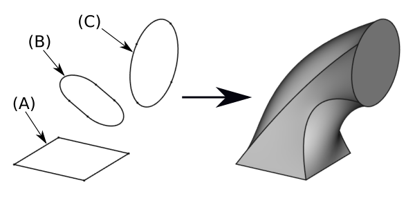
I will say, this type of design is the easiest to do on fusion by far- if you can trace a design using a mouse then you can do it within 10-15 minutes. With these kind of molds it’s generally 3 operations:
-
Import the image you want as a canvas and calibrate its size (this takes 4 mouse clicks). Trace the image using fusions version of the “node tool”.
-
Extrude the sketch you made in step 1 to flat 3d shape.
-
Chamfer or fillet the top edges to get the shape correct. Maybe do a quick loft etc for a rounded top surface as well.
Hardest part of fusion for me was getting the hang of moving the view around.
3 Likes
Any chance using a trace tool on a vector software on the image first, exporting as an svg, then importing to fusion to add depth is a faster way than tracing with the node tool? I hate messing with nodes, but maybe just need to learn to get better at it.
Generally computerized tracing isn’t nearly as good with routers as it is with lasers. If the shape isn’t properly closed you’ll likely be able to tell due to toolpath weirdness.
That is to say you can theoretically do it, but unless it’s a super simple shape you’re probably going to be spending just as much time cleaning it up as you would just tracing it from the jump.
Fusion has some tools that make it nicer to work with when tracing than other (illustrator etc nonwithstanding) softwares have though. Ie if you are tracing a curved corner, there is a tool where you just click however many “points” you want before hitting finish. When you hit finish, fusion will draw the line with the proper curve just based on the points. No need to drag the angle lines between two nodes to get a curve.
Carveco maker is easy to learn. That is what I used for the asmbly American flags in the lobby.
Watch timber falls on YouTube to get going.
Steve, do you mean this Timberfalls?
The two halves of the mold would not be the exact same shape, even when rescaled. A uniform gap would exist between them. And the mold would not be meant to press the clay but rather support it while working the clay from either side as needed.
I’m sure Fusion360 would still be the most straight forward route. And then maybe importing STL files into Carveco Maker. I did get the trial subscription to Carveco to see what it’s all about.
The mold-making process is common in injection molding and composites. You don’t need to export .stls. You could use Fusion for everything.
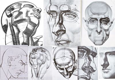
The biggest obstacle would be surfacing your design in CAD. It’s not only the outlines, but also the curvature of the surfaces and how they intersect. It is difficult to make a stylized face, because we tend to notice discrepancies in the curvature. You will have to spend a lot of time getting it exactly right. If you design with abstract squiggles, then it looks interesting even if the surfaces arent very good.
So what I envision is called a slump mold. Slump and hump molds are a thing. They are usually made of plaster to help dry the clay and they tend to be quite expensive. And available molds are all generic type shapes. The mold pairs look like they are positive and negative relief of the same shape i.e. no gap between the two halves.
Regardless of the method, defining the shape is what’s important. For a proper 3d shape you’d need at least one more section, near the ends of the lips. If you drew out a couple of sections you could upload them as reference images in CAD. From there I think you’d be able to get a result with experimenting with splines and lofting . 2D extrusions (or just adding fillets etc.) would just get you a symbolic representation which is not as interesting. There’s a difference reproducing symbols (like hieroglyphs or stick figures) vs. creating a simplified or stylized form, which is what you would get with a loft.
After you have a 3D shape you’re happy with, the rest of the process (i.e. manufacturing the mold) is straightforward. Not necessarily easy, but at least there is a clearly-defined thing to be produced.
Have you thought about 3D printing, at least for a scaled-down test piece? You could even paint Duratec over it (high build primer, forms a hard sealed surface) and use it that way. For bigger molds, milling MDF is a better option – but just 3D printing it would avoid the complexity of feeds and speeds, setting up toolpaths in CAM software etc. (Technically you would still do that stuff, just in your slicer software.)
1 Like
Hello NickE,
Im interested in hiring you to create digital 2 piece mold that i can cut on my CNC. I have 3d scans of my objects and need to to be split profiles on a mold. Can you help?
Most likely!
Please email me the files at nick.emerson@asmbly.org and I’ll take a look.
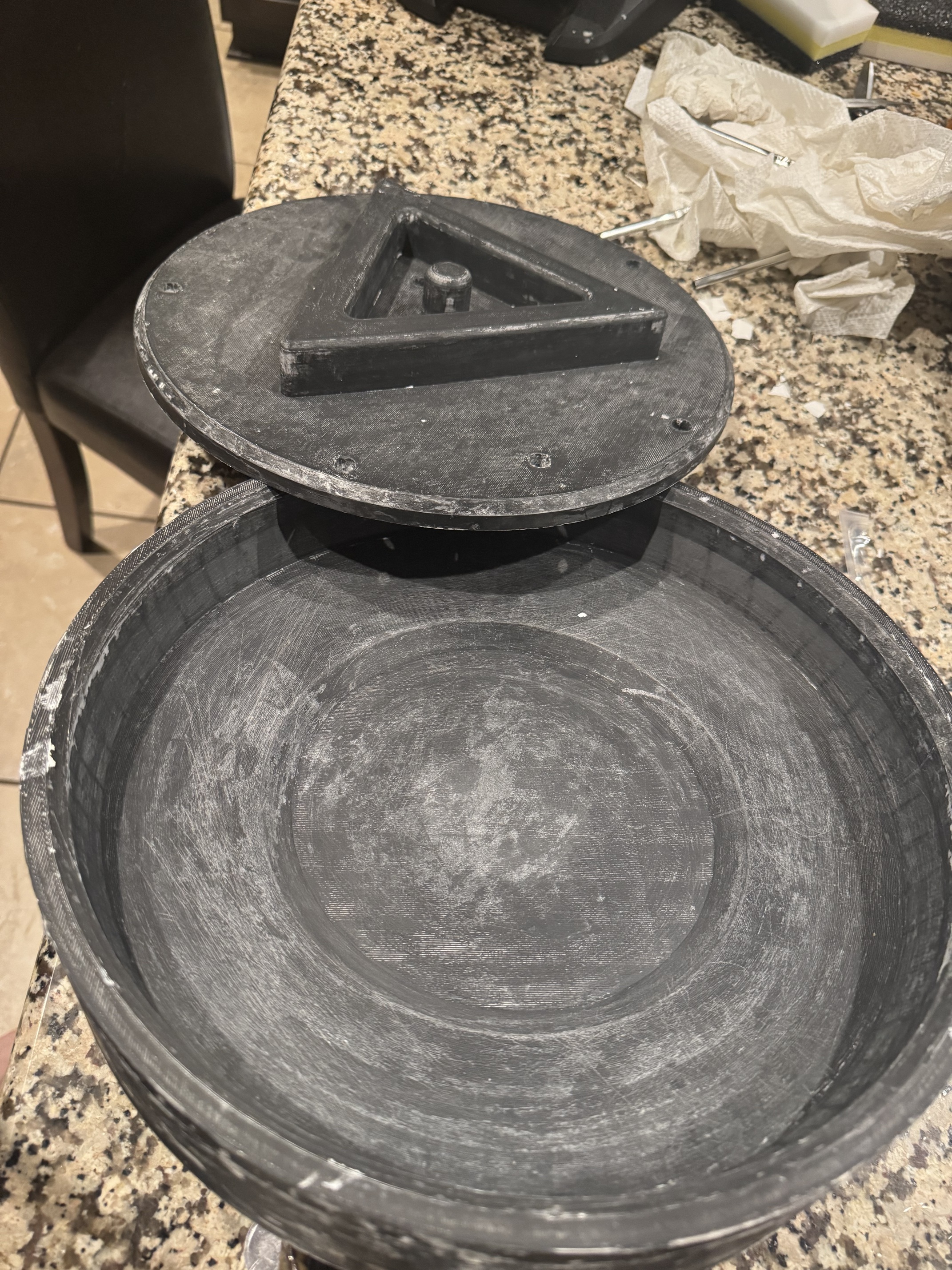
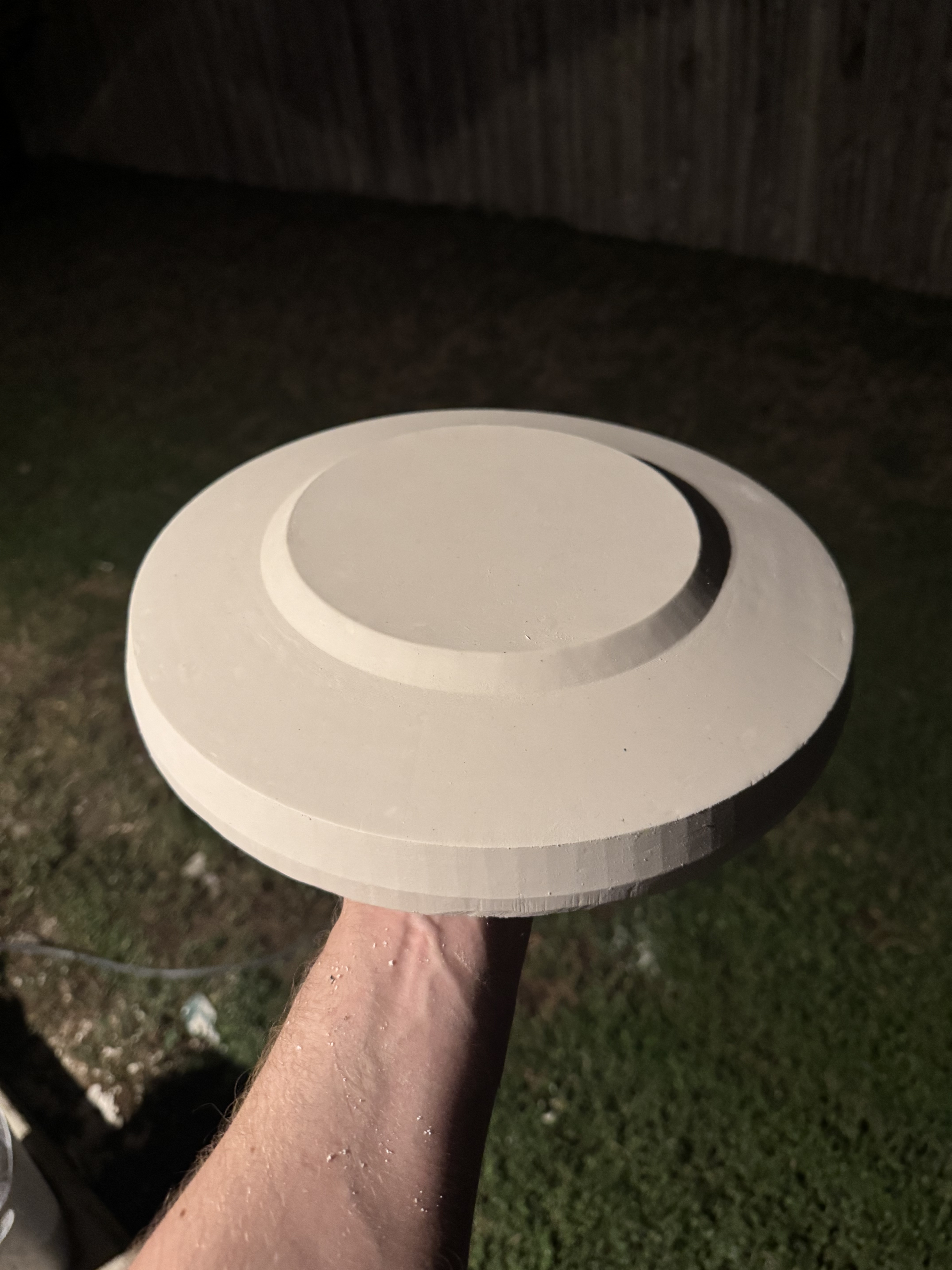
Just made a few for some plates:
1 Like
@NickE in the photos above what is the black/gray-colored mold made out of?
PLA+ in this instance, but it’s covered in both mold release and a film of plaster in that photo. 5% infill, survives being hit repeatedly with a mallet to remove the plaster.
I went with the PLA+ with the best strength rating (surprisingly cheap Elegoo PLA+) per our friends at /r/fosscad. I figure if you can make firearms from it, a mold will do just fine.
I didn’t want to have to do the finish work a CNC made mold would require. These have worked beautifully (I’ve since made a bowl one as well).