@Branislav and @dannym, I think I left my USB drive attached to the Tarkin laser when I exited. Can you leave it on the Tarkin laser desk and I’ll stop by tonight and get it. @bwatt
It was there on the desk last I saw it
I pushed it further. I got it to resolve features under 100 micron! I think I actually got it to perform better than the diffraction limit of the optics.
This required some tweaking. Line interval dropped to 0.04mm, raster the pocket cross-grain, kerf increased to 0.035, and excess power on the veneer part so a small dot would make it through.
I was just trying for “fine”, then realized the foil tape I had is only 2" wide and multiple layers probably wouldn’t work so well. So I threw caution to the wind and tried to render it only 1.75" wide.
Getting the kerf exact is key to rendering thin features. Positive and negative features are different games- a thin negative line on the substrate isn’t that hard, but getting a thin slit in the veneer so that feature shows through is more tricky. Similarly getting a thin slit cut into the substrate is tricky even though the veneer positive feature comes out pretty easily.
Under a microscope, I could see the 0.08mm line interval was making deep valleys between thin walls that stood up like more than 1/3rd of the total cut depth. 0.04mm interval made the bottom much flatter, but it does take twice as long. Not a big issue when the whole project is only 45mm on a side though.
1 Like
@dannym, Thank you, I got the USB drive. Bri
@dannym, if you want any of the 12" wide aluminum please tell me how much and I’ll cut some off for you. I have plenty. Also I really appreciate your help and focus on details today. I apologize for any clumsiness on my part as I’m just a beginner and don’t even know what questions to ask.
Thanks for continuing and writing about it above.
When you said “excess power on the veneer part” - does that means you boosted it from earlier when I was there of 37-40-45% to something more? If so, what was that power or was it just 100%?
A key improvement that the Trotec instructions didn’t have-
Isopropyl alcohol will totally deactivate the adhesive on the foil. It doesn’t dissolve it, it won’t transfer onto the wood, just temporarily deactivate it. It just loses all its stick and actually becomes a slick lubricated surface while wet. Once it dries, it goes back to being sticky.
So I poured some isopropyl into the bottle’s cap and dripped it around the foil tape. The surface tension made it fill in around the loose edge of the tape which can then be pulled off without pulling out the fine features of the inlay. As you pull, it will keep filling in the peel line but it did need another few drops eventually. Best to pull the tape 180 deg horizontally to avoid any residual force pulling tiny features out.
One annoying realization was that, while Lightburn has a perfectly good kerf compensation for vector cuts of closed shapes, it CANNOT be used for Fill, even though those are closed shapes too. And “Offset Fill” does something else entirely which is probably not useful here (although, I’m thinking there may be something to using Offset Fill instead of Fill).
I found rastering as an image was going to present some technical issues that would limit the quality. Instead, I did a Trace on a source bitmap image to create closed vector loops. Then you can do Offset Shapes on the design to achieve kerf compensation. It’s annoying to manage this way- the design is changed with this op, and the number isn’t recorded. That is, if you try 0.04 kerf and it’s too much, stacking a -0.01 kerf on the new line does degrade it somewhat. You want to restart with the original, unkerfed trace and do a 0.03.
Lightburn’s basic undo/redo CTRL-Z/CTRL-Y mechanism is not very robust. I kept trying to back out of the prior kerf op and wasn’t 100% sure if it was where I needed it to be- and these are small changes that are difficult to see if it’s kerfed or not from looking at the lines. I ended up just making a master traced image/mirrored negative on one part of the project and never work on that one, just copy it to the side, resize/kerf, then if I need to adjust I’m going to delete that entirely and make a new copy to work on so I’m not accidentally doing a kerf on top of a kerf.
Once you have a traced image and make a negative mirror below it, you can select BOTH and resize together, and you can also do Offset Shape on both at the same time- the direction is Inward, deselect “Outer Shapes Only” and “Optimize/Simplify Results”, and select “Delete Original Objects”. I believe Corner Style=Corner should be best.
I found that very small lines/dots weren’t making it through the veneer. I though about approaches and figured that giving it more power can drive these partial-thickness features made it through to the bottom while having little effect on the other features. It widens the kerf but not significant enough to matter.
Basically I iterated:
speed 800 power 70 LI 0.08= bottom not flat enough
speed 800, power 35, LI 0.04=twice as many lines takes 2x the clock time. Power reduced by half since we’re taking twice the cuts.
speed 800, power 60, LI 0.04= giving a bunch of excess power to cut the thin holes/slits through to the foil. Just did this on the veneer.
I wanted to start from an SVG file. But most of the “free” image places that have SVG require you to login and most actually require you download their tool to download it (boooooo… boo I say! how about “no”?). Google Image Search will only show a bitmapped version of the file. I found some that had sufficient resolution and not watermarked to play with.
You can buy SVGs from Etsy or wherever pretty cheap, too.
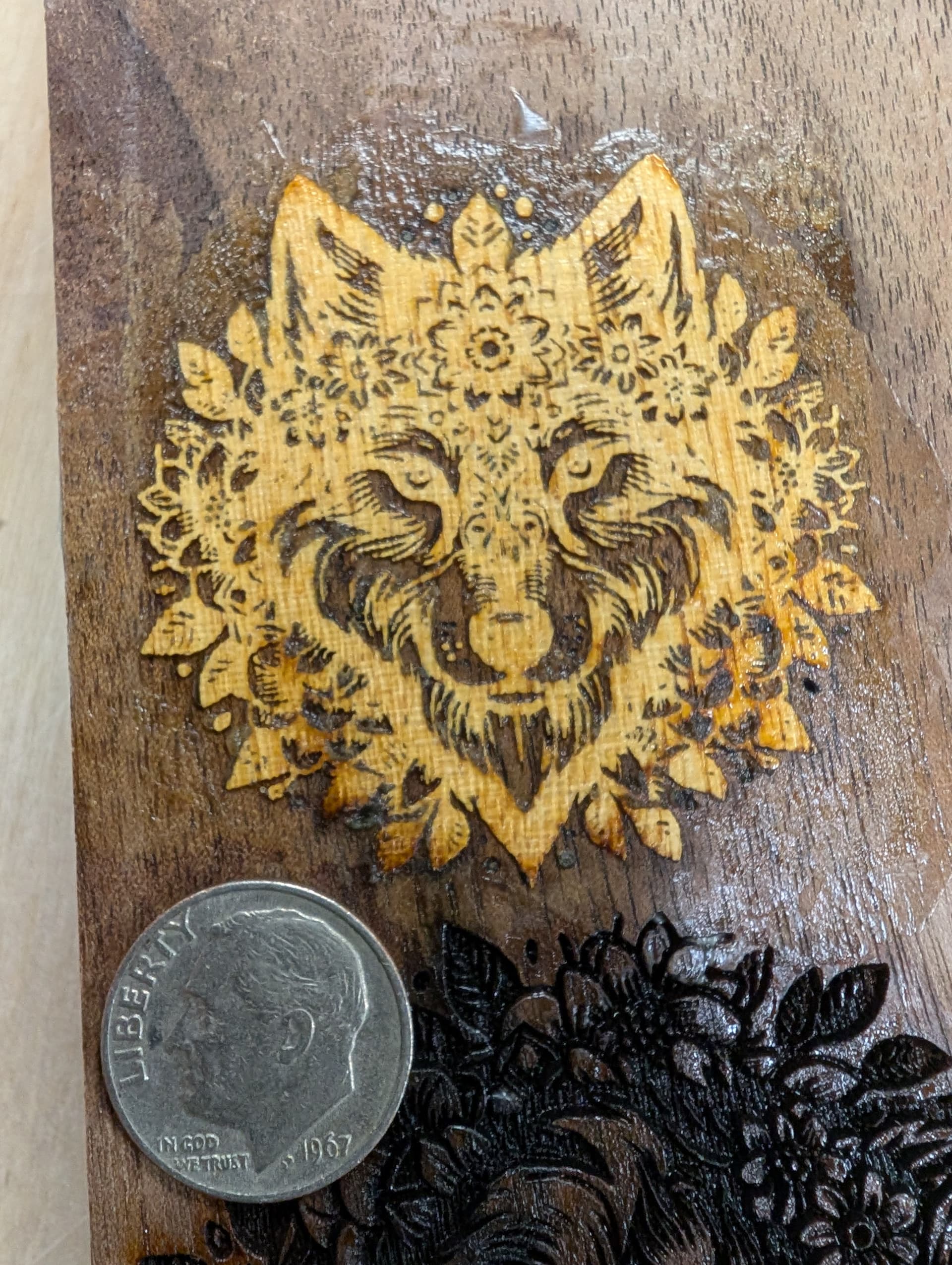
It did occur to me that getting inlays to work on this tiny scale opens up some lucrative jewelry potential- particularly earrings, which need to be small and light. So going from mm-wide features to under 100 micron is a game changer
IMHO doing an inlay of light veneer on a dark substrate is notably more interesting. The case of darker veneer on light would be achievable simply by ink printing, and the casual eye would probably assume that’s the case and move on. But that wouldn’t make the wood lighter, so the lighter veneer’s appearance looks pretty far from ordinary and can get some intense attention.
It does appear the small-scale veneer might not even be possible with ink processes due to ink bleeding laterally through porous wood.
Fantastic work @dannym and @bwatt! Fairly bummed I had to leave before seeing the results but I love the outcome – thank you for sharing the details.
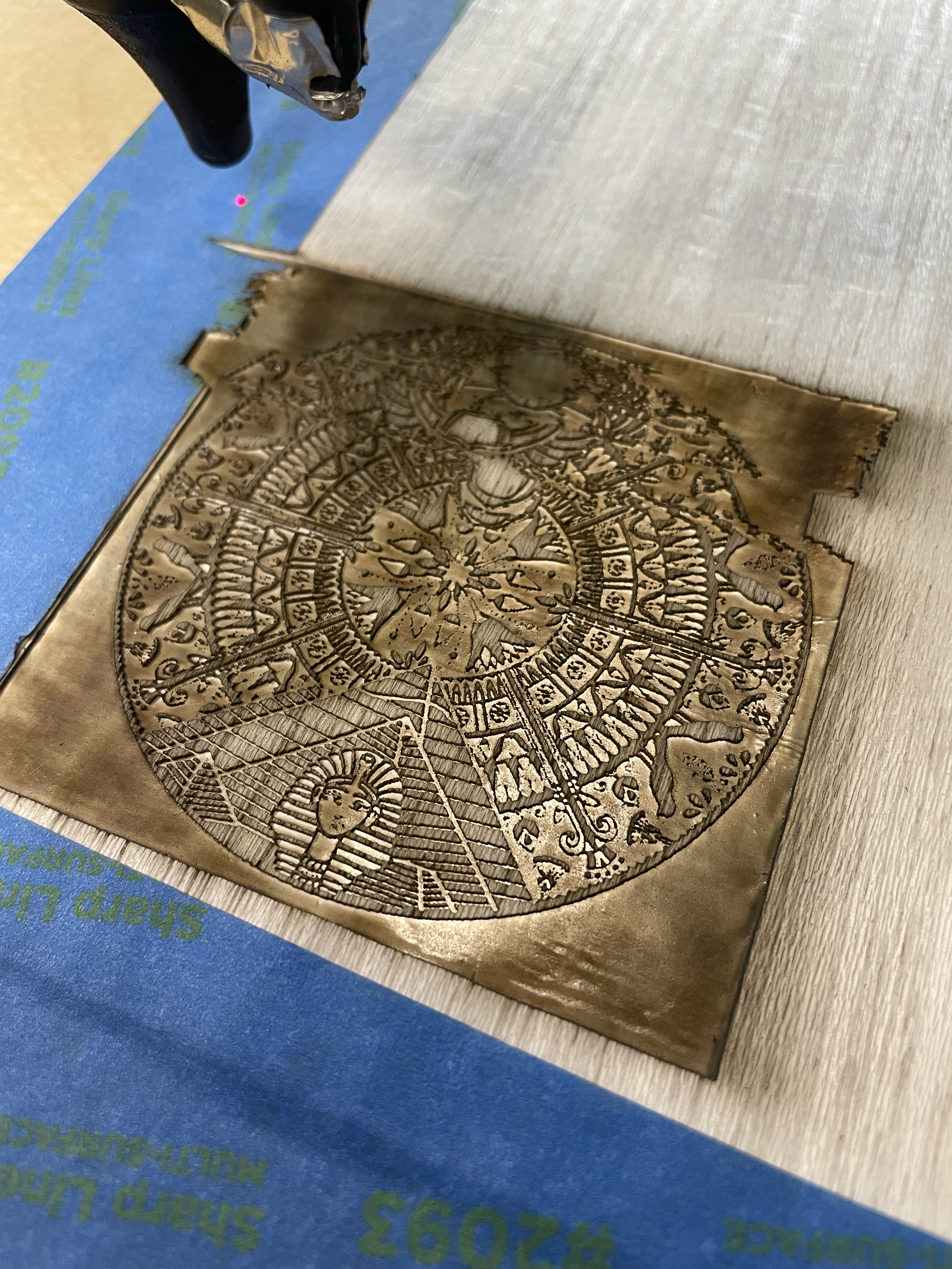
Today I got time to try out the inlay process myself. I kept everything mostly the same [Speed 800, Power 70, Line Interval 0.08, etc.], but I used a raster image and not an SVG one so instead of Mode: Fill I used Mode: Image with Threshold. This seemed to work OK and the results were a very fine detailed filagree of veneer. I did the veneer first then the backing board second, and glued them together.
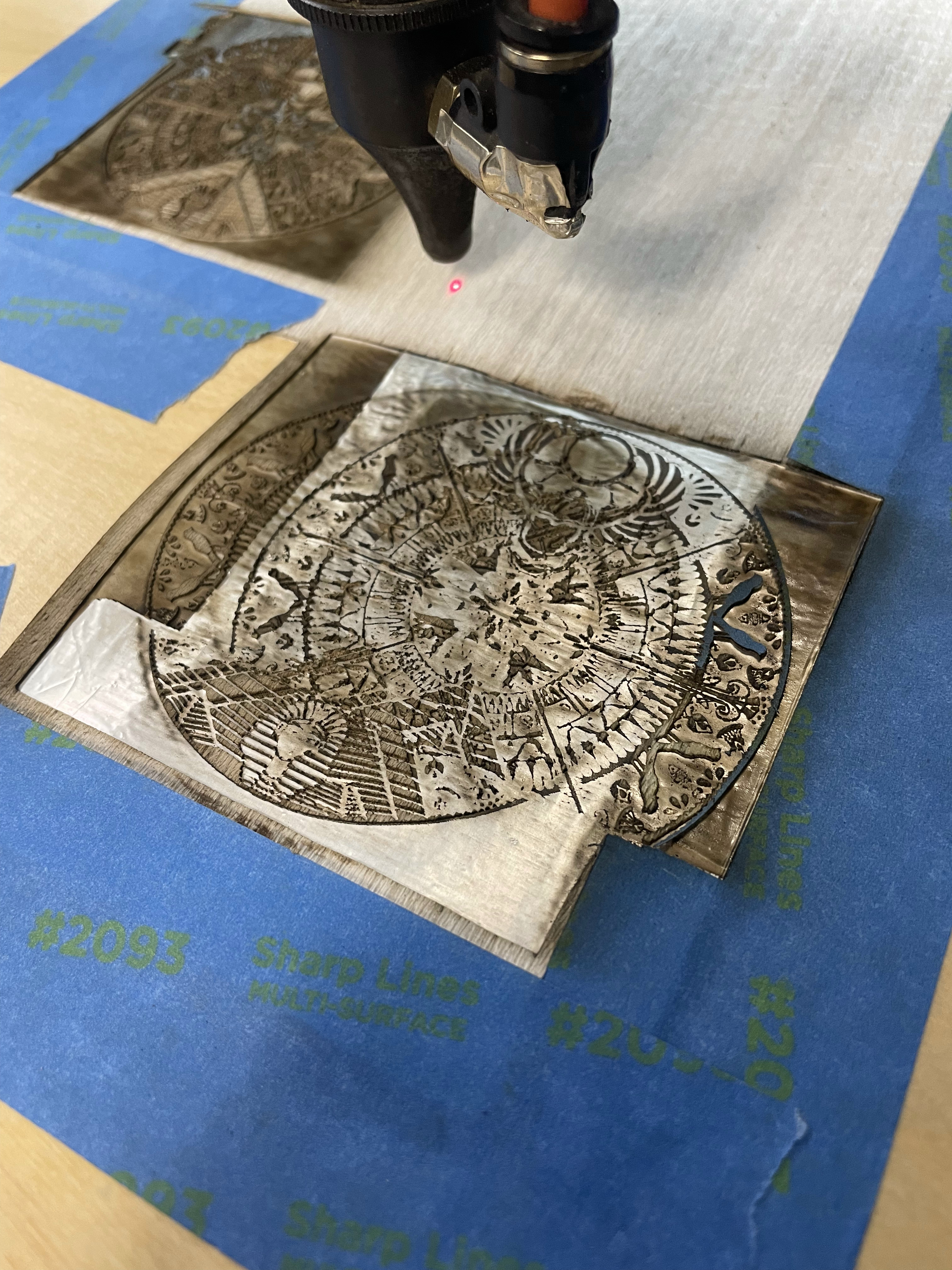
Then I repeated everything the same to show Branislav who stopped by. However, it developed a problem. The rastering shifted the X-axis several times and glitched the image. What the heck? I repeated on more veneer. When doing this one I decided to do a second pass with all the same parameters. The 2nd pass cleaned off the soot that had adhered to the aluminum glue which was great. But then it happened again. Argh! Then one more attempt and I finally did get it to work. So it was kinda random. @dannym I thought you should know.
Could it be we are overdriving (too fast) the communications from the Lightburn system to the Tarkin laser?
See pictures below.
I dont think your technique or set-up is at fault. I also did some rastering and some pieces were distorted but all the other ones came out right. The distorted pieces were kinda in the center of the table. Danny did look at them. He explained that the motors auto correct their position thats how not all the pieces ended up distorted for the rastering part. However cutting or vectors did not experience the same effect. Maybe people should be on the lookout for this anomaly as Danny did not look into it any further.
with it happening a second time, this has my attention.
what raster speed was this at?
I tried this technique today, and was unable to get my veneer to cut properly :(.
I’m not sure if this is due to the actual art I’m trying to engrave, the kerf, or something else.
I started with an SVG, and followed the instructions in the video above + used the settings Danny mentioned above.
Ran a few passes on 35% as well and it seems to have helped, but still no dice on something useable.
1 Like
@dannym I was using the settings that you and I had used a few days ago when we were together: Speed 800, Power: 70, Line Interval: 0.08. My piece was 3" square. I was using the lower right quadrant of the bed. Originally I felt it might be bed location near the center of the bed, but then I moved it closer to the front and right about 12" from each, and still had the problem.
@nick, it looks like you were trying to cut the aluminum side, were you? It just might be the picture and how I’m seeing it. Also how big are your pieces? How many passes? Danny and I were doing 1.5" squares for the flower one pass, later for the egyptian I was doing 3" squares one pass. What is your criterion for “something useful”? I felt your last one looked good enough to glue it on a base piece.
are you sure you kerfed it the correct direction?
it needs to thin out the black areas being cut, on both the positive and negative
Cutting the veneer side.
The strips of veneer in the pic are 2” wide, image is 1.75 or so.
Single pass (tried double at first but it blasted away almost everything)
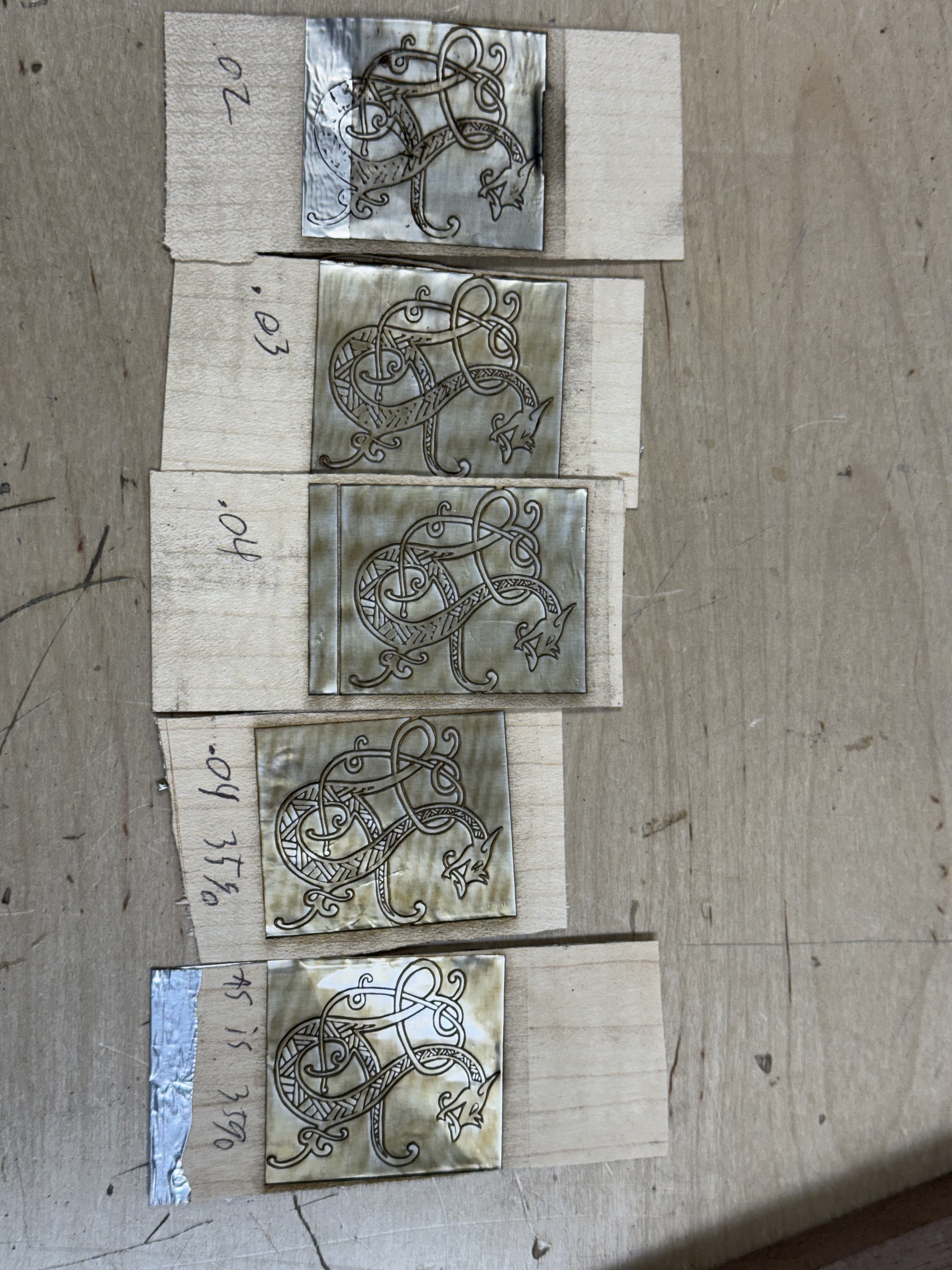
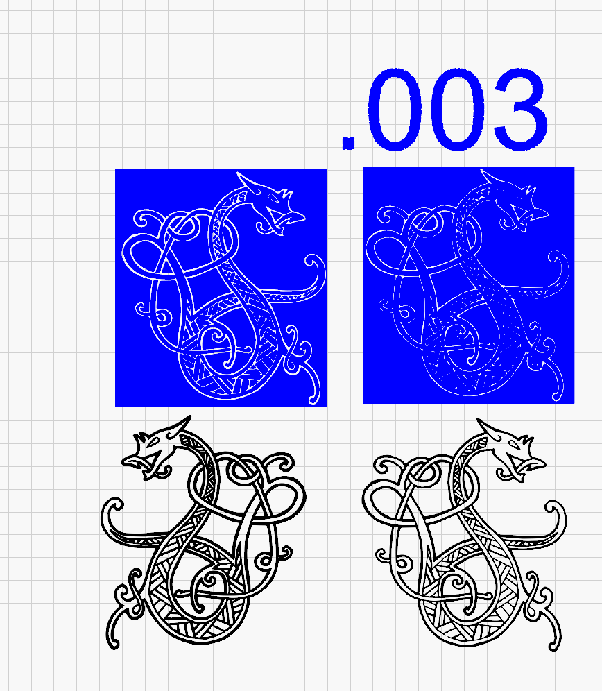
Re: “useable” - see the attached photo for what the cuts should look like. The last one is ok, but still missing a decent portion of the inlay.
I do think I may have not been setting up the kerf correctly, or the steps may be different due to the artwork used. When looking for a noticeable difference when doing the offset objects I couldn’t see anything changing until dropping to .0015.
Kerfing needs to make the filled area recede, making unfilled lines wider
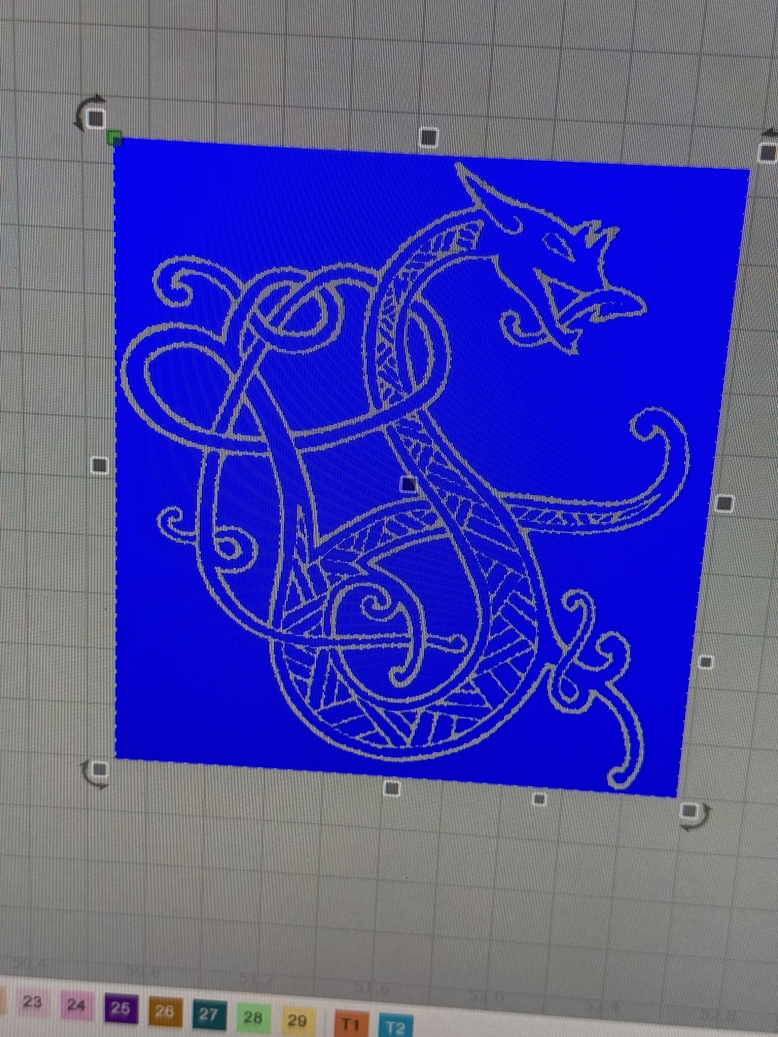
Gotcha, I was a few decimal points too high for the scale I was working in lol- got it to work properly at .003! Thank you!
1 Like
One thing I worked out is the kerf needed for a tight match does vary with how deep you’re cutting the pocket, but also wood type. Cutting shallower means the beam needs less kerf offset, but the path cut by a focused beam can generally only be as wide as about 0.2mm, so 0.1mm offset max for the deep cut and potentially less for shallower.
But that’s not the only factor. The depth and width a beam actually cuts is a matter of wood density, and wood grain density variation causes that depth and width to vary. In some woods it was minimal, in others if you look under a microscope you can see dramatic ridges and narrow valleys slot between them. Oak was particularly bad. Maple and walnut less so.
This isn’t true of the veneer side though- I just straight-up doubled the power I used for the pocket and there will be no ridges left. The cut edge gets pretty vertical and most of the beam’s focal dia is already cutting so the kerf offset won’t vary much with thicker veneer or denser wood.
I did a larger one and definitely had more trouble aligning it. I’m getting a better kerf calibration together soon.
The benefit of being precise here is, ideally, you can press-fit the veneer in while gluing. Actually I the best results by tapping it in with a hammer. That works with surprisingly fine features, in fact it needs to be pressed in to fit the finest features.
For a feature to successfully render, you need some of the substrate surface and some of the veneer surface showing on the outer face. So by definition we’re trying to reduce the width of the glue-filled gaps but the substrate side has walls that have a slight slope and varying degrees of those density ridges drawing into the gap area. That also means we need the gap to be spread equally on substrate and veneer so we can shoot for the smallest line where both still reach the surface in the final cut.