Thanks @JoeN. I was there measuring for the plotter attachment I’m needing at 8 PM tonight. We must have just missed each other.
I was there a bit earlier. I can possibly meet today? I have a scheduling thing I’m trying to resolve. How about 5pm tentatively?
Oh, sorry, I just got your note after work and attending DockerCon 22. Also I’m a new member and would want to work under the guidance of a more seasoned steward to make sure all the proper procedures were followed.
I went to ASMBLY today, saw the end plates and clamps. Looking good! I also got the dimensions of the table so I can build a CAD model of the table.
One of the things I roughly determined is the specifications of the size of stock that could be processed. Using the table coordinate system, presently the X size is 43.5", Y size is 2.5", and Z size is 39.5". These are approximate. If possible, I would suggest that we increase the X size to 48.5" to allow a standard 4’ piece of stock to be mounted. In other words, the long edge of a 4’ x 3’ x 2" panel could be handled.
Thoughts?
The drawn measurements was a just a guess. If you want 48.5" that is fine. It makes sense for people who want to work a 4’ board.
Let me know when the cad is done. We can start planning from there
@JoeN, will do, it’ll be few days, life has gotten busy for me.
I have a “Honey-Do” job to design some jigs for putting in some edge and surface holes (that could have been done using the end mount if it were available).
Something I’ve been pondering… On making any “tool” you always try to make it fit the immediate project, but also to be general enough to adapt to follow-on project needs. With that in mind I’ve always been assuming the end mount would be 90 degrees to the spoilboard, because that’s my immediate requirement. However, there might be a future need to be something other than 90 degrees, for example, 45 degrees or even 30 or 60. So how would we design it to enable that. The chop saw has detents, the joiner can angle its side board too. Is there something we could incorporate without a lot of fuss to do this? And always it’s got to be finely adjustable to insure accuracy across the piece being worked. Hmmm, thinking about this…
I hadn’t planned on anything beyond 90 deg. I think something beyond 90 deg. We can make wedges that bolt into the jig plates giving the needed angle. I think a few common angles would good. I think using a hardwood is best.
OK, for a first pass I’m assuming a 90 degree end mount.
Here are some screen shots of the CAD model of the CNC with the End Mount. Is this close to what you were expecting?
Annotated see-through proposal.
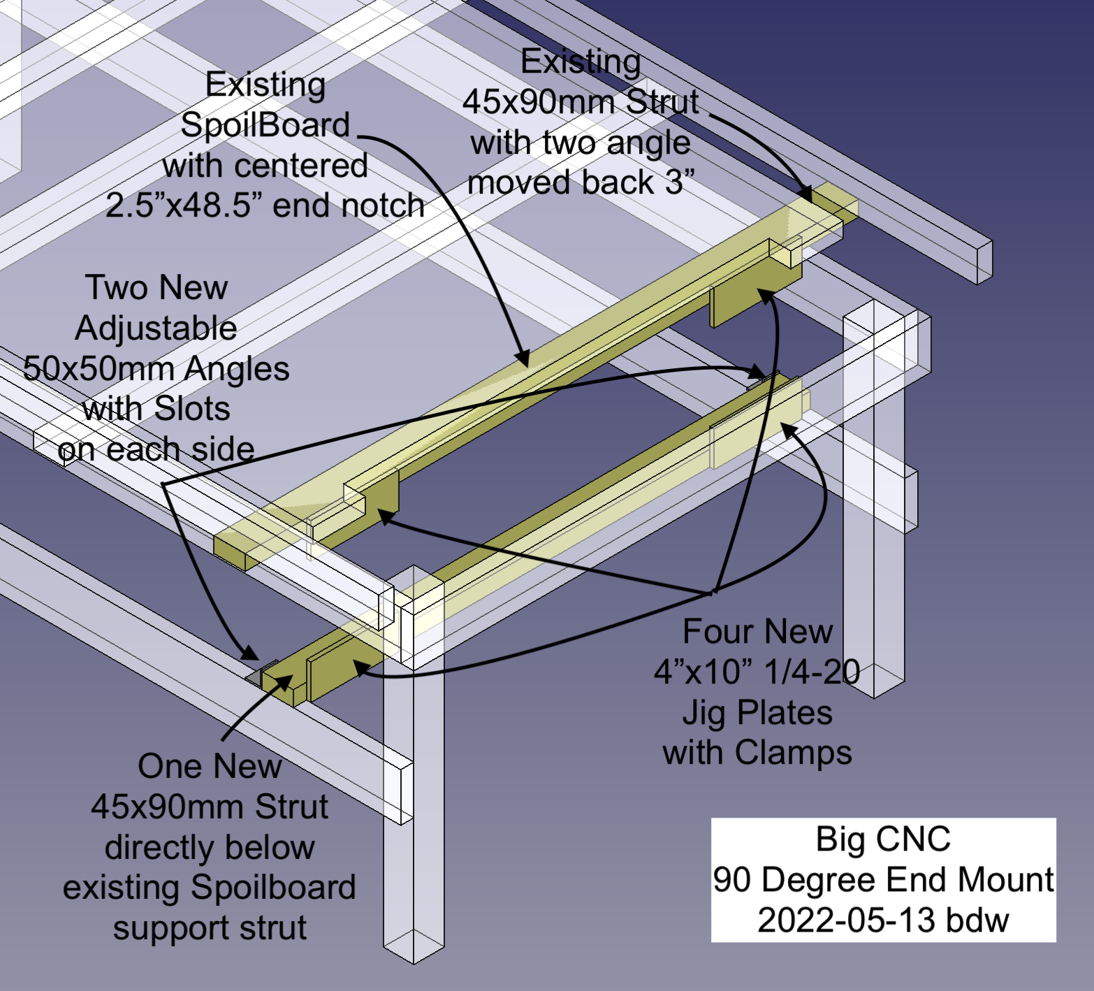
P.S. I’ve been debating in my head whether we should include a spoilboard on the end too. It’s not that the end mills would affect it much, but people could screw into it to hold their work, because they are used to doing this on the horizontal spoilboard. I would make the end notch larger by about 2 inches. Thoughts?
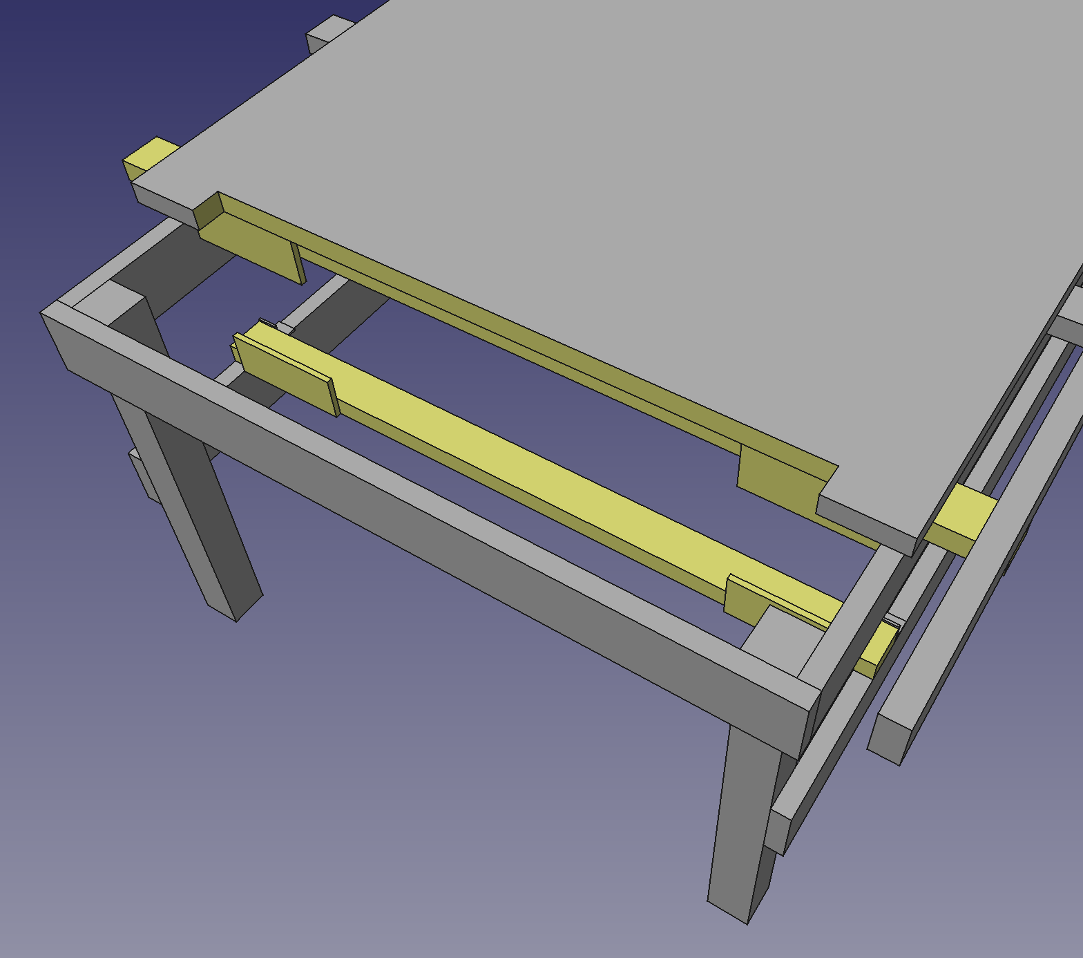
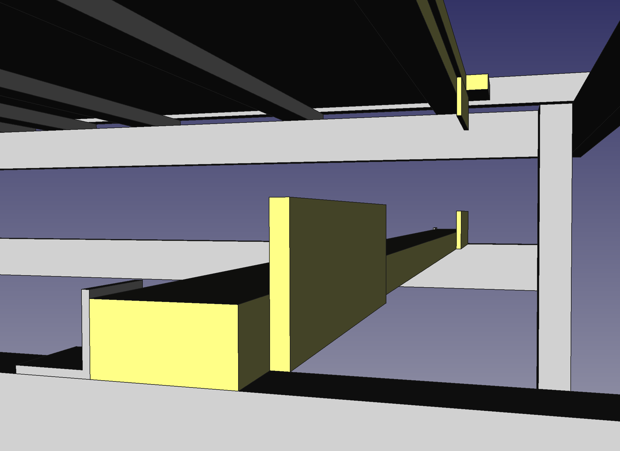
Some perspective views.
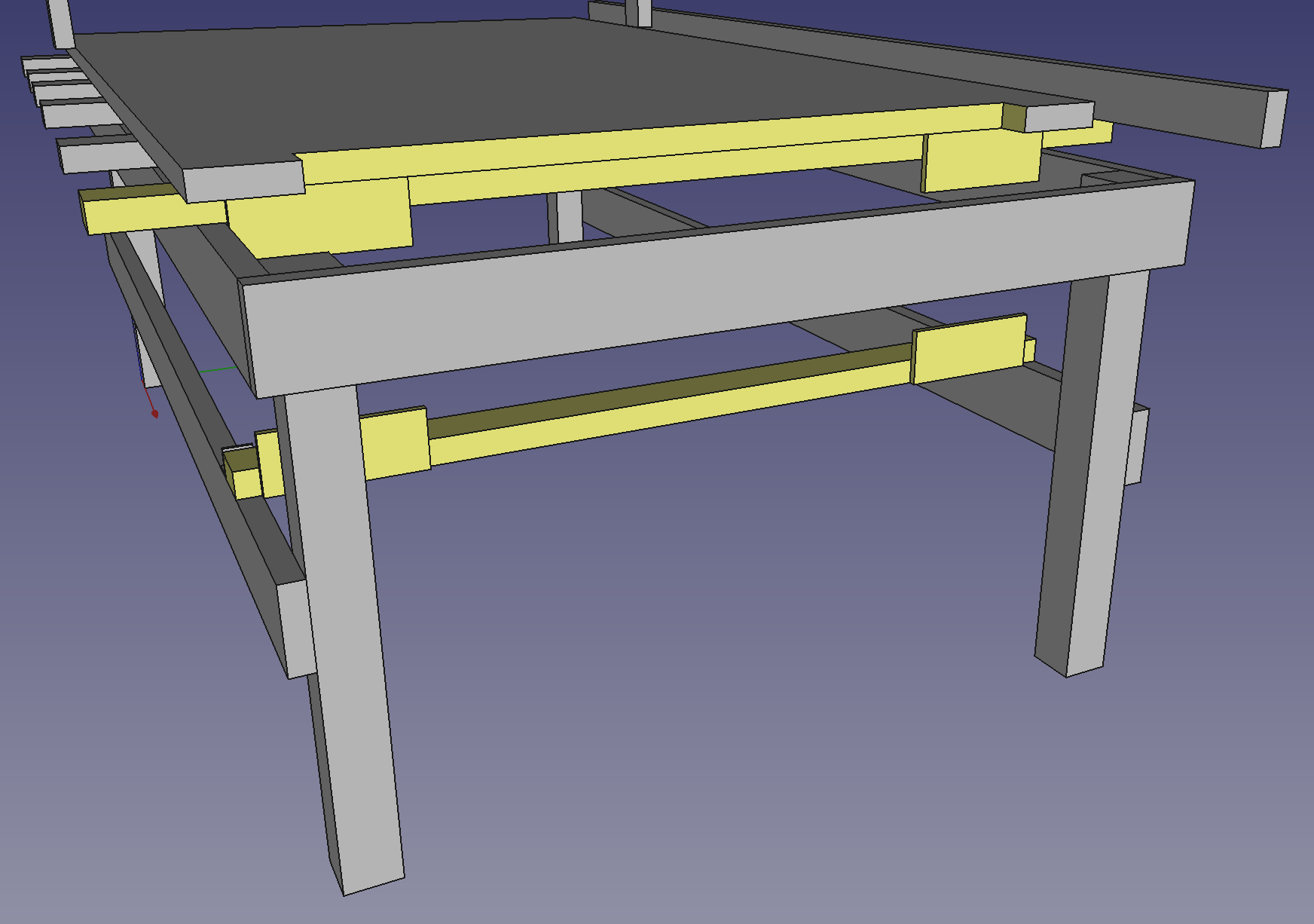
That is great. I like the addition of the bottom support.
Maybe: If you move the clamping surfaces in a bit more you won’t have to reduce the size of the main spoilboard?
@zackg, the main spoilboard has to be notched, in other words, moved-in, because the X carriage does not extend beyond the spoilboard. In other words, the spoilboard currently extends beyond the X carriage limit.
I was thinking about this project. I fully support the 90 design. I don’t have a bunch of bandwidth to see the project morph into a multi-angles or other functionality. I’m not saying stop designing. I’m jumping off after the it is installed. I’m leaving town for a while in June and would like to wrap it up before then.
@JoeN, First off I greatly appreciate meeting you even though the circumstances were a bit stressful because you were trying to start your metal lathe class. Thanks again.
Like you it’s beginning to be summer and that means vacations. I’ll be away from this Thursday May 19th to the May 28th. And then you’re leaving town for your June time away. So this might take a bit longer.
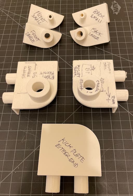
Something the new end mount could have aided. I wanted to show you what I had to make to “shortened” an IKEA shelf unit from 31" to 27". It required me to cut a new set of end and side holes. This included ones for the permanent shelves that hold the unit together (middle two). Wouldn’t you know it that the hole distance from the front was different than the back so I needed two of them. Then the bottom kick plate which was held in by towels (bottom one). Finally for the movable shelves that have little diecast “shelf supports” (top four). All 3D printed to act as locators and drill guides. Sheesh!
@bwatt It was nice meeting you as well. Are you missing the Asmbly Party? The cnc router issue was a little stressful, but it also trains you to think through problems and hopefully solve them. I’m probably not leaving till about mid June. Let’s work to get it done.
@JoeN, Yes unfortunately I’ll be away attending my daughter-in-law’s graduation as a Doctor of Physical Therapy!
Some of the things I’d like to do is create (1) a list of tools needed for the conversion, (2) a list of parts needed, and (3) a detailed step-by-step procedure to accomplish it. Then I’d like to get it approved before doing the work. All to make the actual work planned and easily executed.