What do you actually want to make with CNC—and what gets in the way?

Hi everyone,

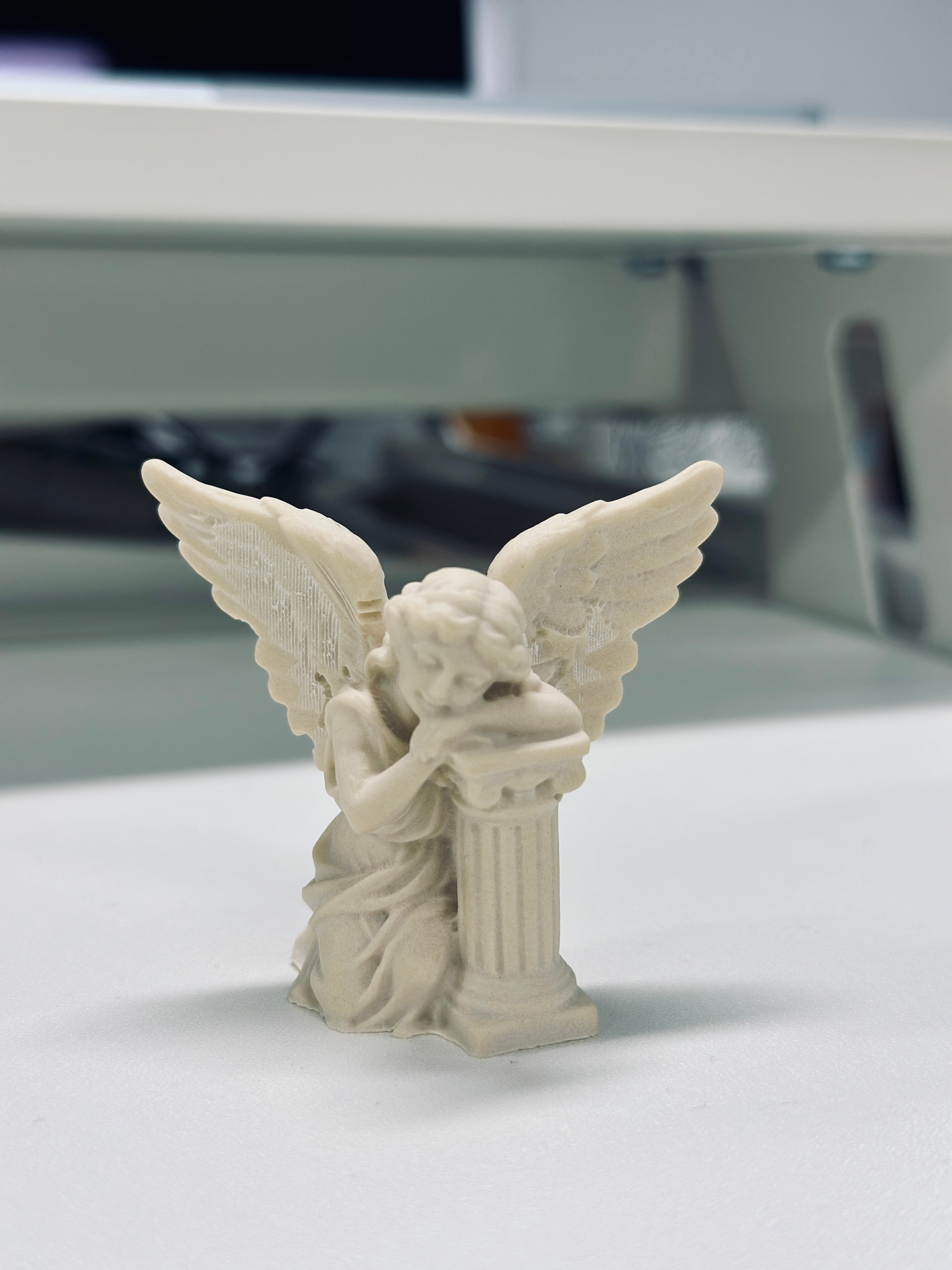
I joined the CNC Creators meetup at Asmbly in June and really enjoyed the discussion. I was the person who showed photos of the angel model made on a five-axis CNC.

What made that experience unusual was that I had no CNC programming or machining background. I was able to make the model because much of the programming and setup had already been simplified for me. It made me wonder how many more people might use CNC if the workflow were easier—but also what experienced users actually need beyond “make it simpler.”

My team is now developing Skera, a compact enclosed CNC concept, and before making more product decisions, we want to better understand real projects and real frustrations. This is not meant to be a sales post—we are mainly hoping to learn from the community.

I’d love to hear about any of the following:

  1. What is one CNC project you have made recently—or really want to make?
    Photos, CAD screenshots, or work-in-progress pictures would be great.

  2. How do you currently make it?
    For example: Asmbly’s CNC, manual tools, laser cutting, 3D printing, outsourcing, or a combination.

  3. What part of the process causes the most trouble or takes the most time?
    CAD/CAM, choosing tools, workholding, zeroing, setup, machine access, cleanup, or something else?

  4. Have you ever delayed, simplified, outsourced, or abandoned a project because the CNC workflow was too difficult?

  5. What would make a new CNC machine genuinely useful enough for you to try—or eventually buy?

Short answers are completely welcome. Even one project photo with a few sentences would be very helpful.

Thank you again to everyone who spoke with us at the meetup. The conversations about fourth- and fifth-axis machining, software difficulty, and the gap between taking a class and completing an independent project have already influenced how we are thinking about Skera.

Hi Serena Li, I would like to make a coupler that would connect the top of the propeller shaft of an outboard to an electric motor. I have disassembled the dinosaur fuel motor from the propeller shaft to expose the toothed pin where the motor attached to and now need to create a custom coupler with teeth that would fit on it on one end, and on the other end fit into the electric motor. Can your 5-axis machine create this part in stainless steel? Thanks, Anthony

1 Like

I’ve done a bunch of CNC projects at Asmbly and elsewhere (I have been taking machining classes at Austin Community College).

  1. Here’s a writeup of one of my recent projects that had a CNC component: Advanced Fabrication — Not @ Work (search for CNC to jump to the relevant parts). Here’s another: Winter Break — Not @ Work . And these projects used both wood and metal CNC’s: Maker Chip Challenge — Not @ Work

  2. I’ve worked on all three of Asmbly’s CNC machines (both Laguna CNC Routers and the Tormach CNC Mill). I also routinely use manual tools and 3D printing in projects that have CNC components.

  3. A big challenge is designing to replace or interface with an existing part. Measuring the exact placement of holes, figuring out tolerances, and capturing complex shapes are all tricky. I’ve done a fair amount of working over photographs, but correcting perspective is hard. I often 3D print my part multiple times to dial in the fit before firing up the CNC. Asmbly has a 3D scanner, but I don’t like working with meshes much, and fear that the cleanup wouldn’t be worth the trouble.

    Another challenge is workholding, especially for parts that need multiple setups. I often have ridiculous combinations of vises and strap clamps.

    Cleanup at Asmbly is also a challenge. I really miss the coolant hose + chip auger cleanup from ACC’s Haas machines. Being able to just hose all of the chips to the bottom of the cabinet is much easier than Asmbly’s Tormach process of squeegeeing, blowing with compressed air, and shop vacing. More than once I’ve come in to find the machine covered in chips because the last person didn’t do a good job.

  4. Yes. :slight_smile:

  5. Interactive CMM to measure an existing part would be awesome.

1 Like

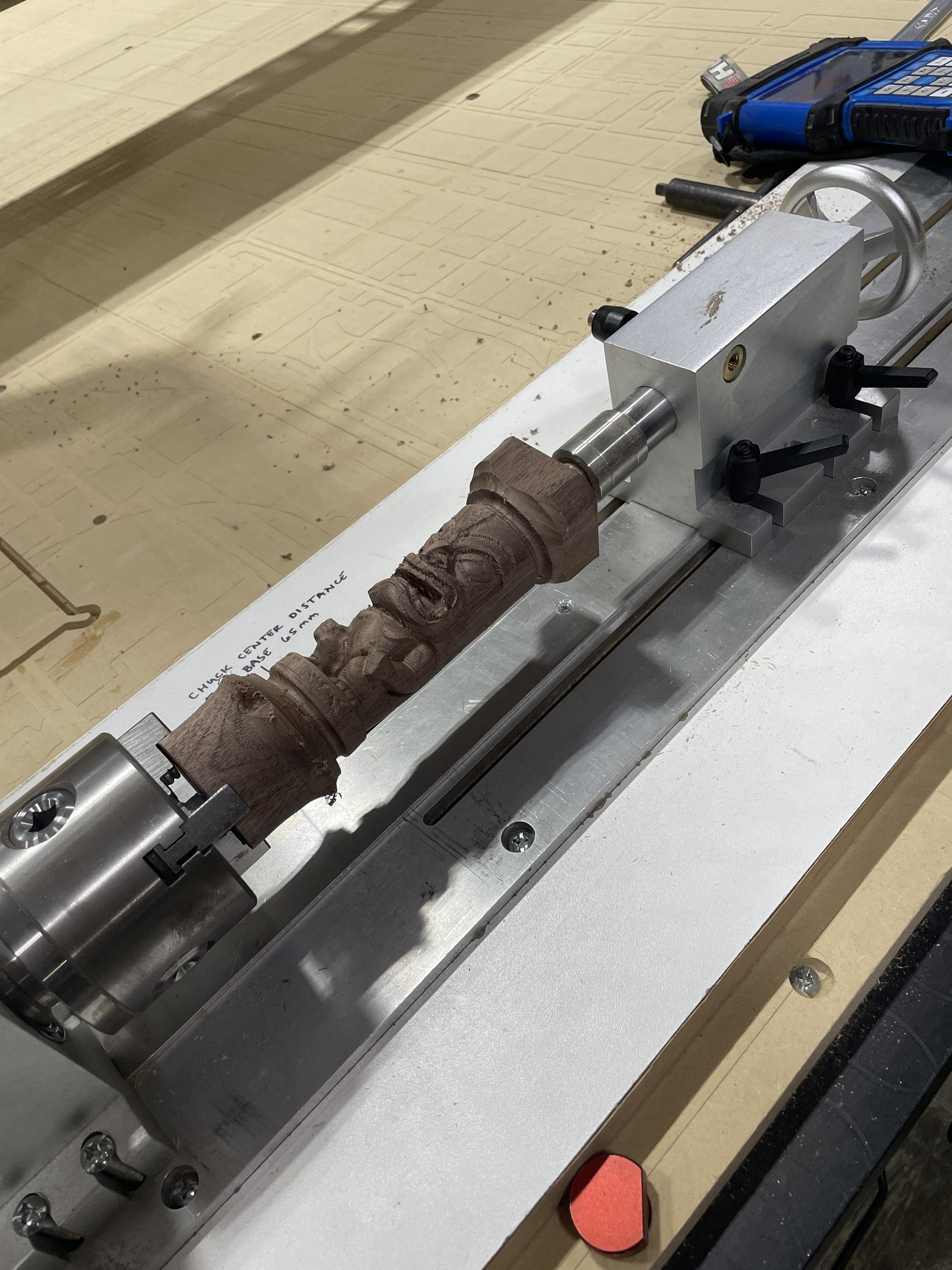
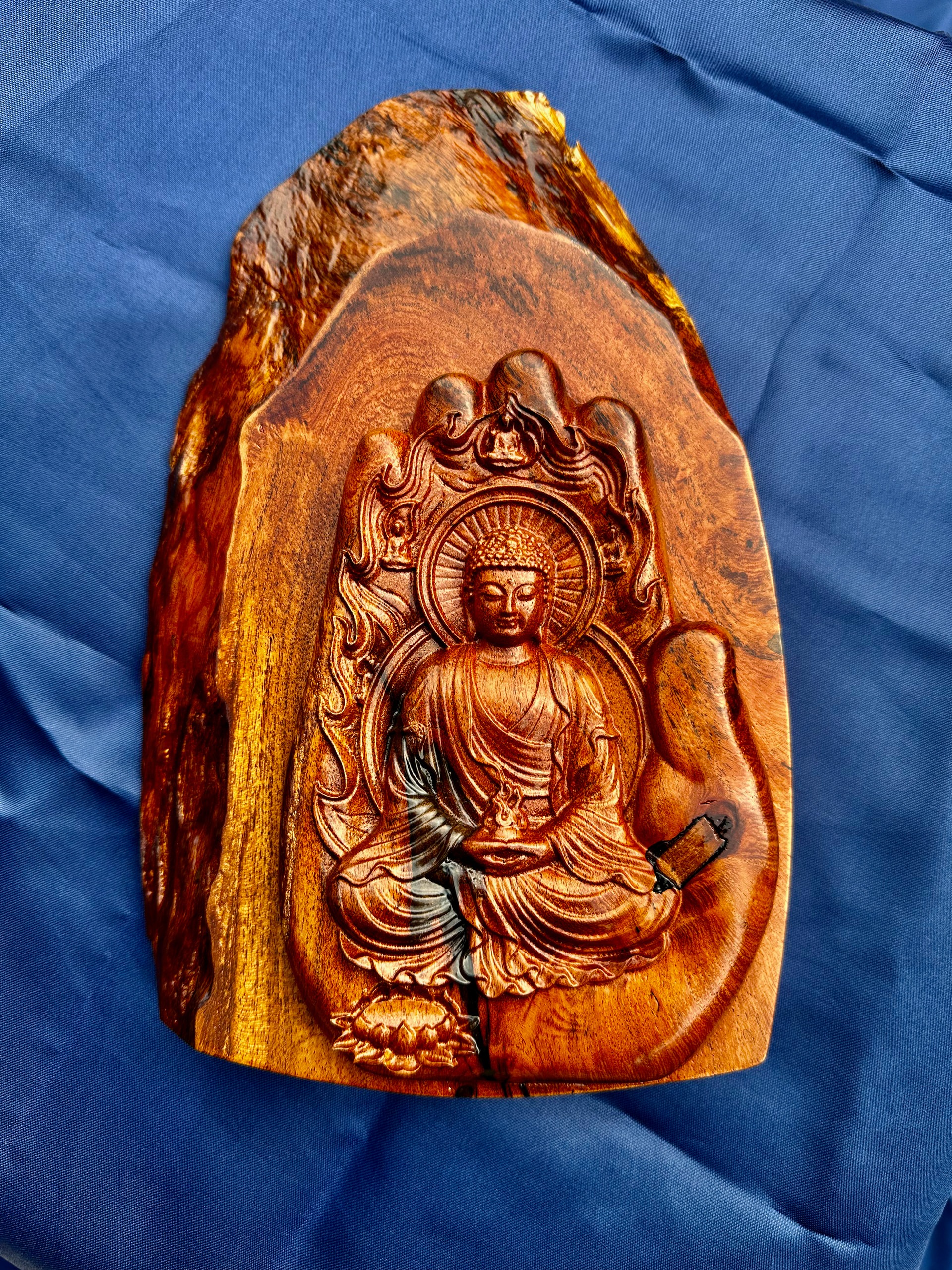
I did a 3d carving of a model I downloaded using fusion for the CAM. It was very tricky to do the CAM, since it would often just fail to generate a toolpath due to the complexity. Eventually I figured out what to do and not do, but it’s not always simple to just crave out a random stl.

With the tiki, there are some areas in the mouth which the tool cannot reach and the tool path would always want to carve too deep or not at all. This required some creative CAM solutions. Since I was using a raw STL in the CAM, options are limited there on what you can do, since you cant select individual faces like a solid model. I don’t like modifying STLs and I’m only capable of doing very simple things with them if at all.

Vcarve might be a bettion option for complex 3d like this, not sure.

1 Like

Thank you so much for the detailed response and for sharing the project write-ups. Your experience across Asmbly’s Laguna routers, the Tormach mill, ACC’s Haas machines, manual tools, and 3D printing gives us a very useful view of the full workflow rather than just one machine.

A few points from your response were especially valuable to us:

  • Designing a new part that has to replace or interface with an existing part is a major challenge, particularly when locating holes, determining tolerances, and capturing complex geometry.

  • Repeated 3D-printed fit checks are useful, but they also show how much effort is required before the final CNC operation.

  • A 3D scanner does not necessarily solve the problem if the result is a mesh that requires extensive cleanup.

  • Workholding and repeatable positioning become especially difficult across multiple setups.

  • Chip cleanup is not only inconvenient—it becomes an operational problem in a shared shop when the previous user does not clean the machine properly.

Your idea of an interactive CMM is particularly interesting. We have been thinking about whether an in-machine probe could guide users through measuring features such as hole centers, distances, edges, planes, and curved profiles, and then turn those measurements into usable reference geometry rather than just a raw mesh.

When you imagine an interactive CMM workflow, would the most valuable outcome be:

  • accurate measurements displayed to the user,

  • automatically created CAD reference geometry,

  • automatic alignment of a new design to the existing part,

  • or some combination of these?

I’d also be very interested in hearing about one specific project that you delayed or abandoned because of these challenges, if you are comfortable sharing it.

Thank you again—this is exactly the kind of real project experience we were hoping to learn from. If you would be open to it, we would also be glad to schedule a short call at a convenient time to discuss the measurement, workholding, and cleanup workflows in more detail.

Thank you—these photos and the explanation are extremely helpful. The relief carving and the rotary tiki also show two quite different kinds of 3D CNC work, which makes your experience especially useful.

Your response really highlights that “download an STL and carve it” is still far from a simple workflow. Even when the model looks fine visually, Fusion may fail to generate a toolpath, choose an unsuitable depth, or leave areas unmachined because of tool reach and geometry. The fact that a raw STL does not provide selectable faces like a solid model also seems to make local corrections much harder.

The mouth area on the tiki is a particularly good example. It sounds like the real challenge was not only generating a toolpath, but understanding:

  • which areas the current tool could not physically reach;

  • whether a smaller or longer tool would help;

  • whether the setup or rotary angle should change;

  • and which details would need to be simplified or left unfinished.

This is very relevant to what we are considering for Skera. One idea is to analyze an STL before CAM and visually highlight:

  • reachable areas;

  • areas requiring a different tool or orientation;

  • details that will be lost;

  • and geometry that cannot realistically be machined.

The software could then suggest a smaller tool, another setup, a different machining angle, or a localized model adjustment instead of simply failing to generate the toolpath.

I’d be very interested in two follow-up questions:

  1. When you finally got the tiki toolpaths to work, what changes or workarounds made the biggest difference?

  2. In an ideal workflow, would you prefer the software to automatically simplify or repair the STL, or to highlight the problematic areas and let you approve the proposed changes?

Thank you again for sharing such a concrete example. If you would be open to it, we would also be very happy to schedule a short call at a convenient time to discuss the STL, tool-reach, and rotary CAM workflow in more detail.

Hi Anthony,

Thank you for sharing this—this is a very interesting and practical use case.

From your description, you are converting an outboard from a combustion engine to an electric motor and need a custom coupler that connects the existing toothed or splined propeller-shaft interface to the electric motor shaft.

A five-axis machine may be able to produce much of the part, including the external geometry and multi-sided features. However, we would need to inspect the exact tooth or spline geometry before confirming whether the entire coupler can be machined directly.

The most important question is whether the toothed connection is an external spline, an internal spline, or a proprietary tooth form. A deep internal spline may require a specialized process such as broaching, gear shaping, wire EDM, or a custom tool, even if the rest of the part can be machined on a five-axis CNC.

Because this is a rotating load-bearing component, we would also need to understand the torque, speed, fit, material grade, corrosion environment, and balance requirements—not only whether the shape can be cut.

Would you be able to share:

  • clear photos of the toothed shaft and the electric motor shaft;

  • the tooth count and approximate dimensions;

  • the motor model, maximum torque, and RPM;

  • whether you still have the original mating component;

  • and how many couplers you would need?

If you have a drawing, CAD file, or even measurements taken with calipers, those would also be very helpful.

Thank you again for bringing us such a concrete project. It is exactly the type of custom repair and conversion application we are interested in understanding. If you are open to it, we would also be happy to schedule a short call at a convenient time to review the part and discuss possible manufacturing approaches in more detail.

Best,
Serena

Hi Serena. Your response reads to me like it was generated by a large language model. I’m happy to talk with people about this stuff, but I’m personally uninterested in interacting with plagiarism machines. Apologies if I’m mistaken about the response.

2 Likes

I’ve spoken with Serena in person after our last CNC Sig. She is very sincere and had a great presentation at the Sig, along with a real desire to help the CNC community in general.

I believe her response is genuine. It may be translated, as I believe English is not her native language.

1 Like

Hi aneel, thanks for being direct. I understand and I’m very sorry to make you feel this way.

English is not my native language, and since I have almost no professional background in mechanical equipment, when discussing technical subject, I used an AI writing assistant to help organize and polish my reply, to ensure that I can express my thoughts and needs more accurately. Again, I’m sorry the response came across as impersonal or insincere, I should have written more simply and in my own voice.

I respect your preference. If you’re still open to talking, I’ll try to respond in my own words from here. Or I arrange a short call and include one of our engineers if that would make the discussion more useful.:smiley:

1 Like

Hi James, thank you so much for saying this. I really enjoyed meeting you at the CNC SIG.

English is not my first language, and I did use AI and translation tools to help polish my reply. The interest and questions were genuinely mine, but I understand why the response felt impersonal. Thanks again for your understanding, I’ll be more careful about using my own words in the future.

Thanks, Serena. As I said, I’m happy to talk with people about this stuff, but the bullet points and restatements made me feel like I was talking to a machine. I understand why it’s uncomfortable when you’re operating in a different language. I often need to look things up when I am writing in Portuguese, and I’m never sure whether my writing sounds strange to native speakers.


To answer your question about CMM: I am comfortable in CAD, so my ideal output would be a STEP file or something similar.

As an example, I made a replacement for the aluminum part in this photo: Factory vs 3D Printed | Aneel | Flickr . I imagine telling the CMM that I want a rectangular block and then using the probe to touch the four sides and the top to get the dimensions. Then I would move the probe into each of the screw holes and ask it to measure a circular bore. I could get the rest of the shape by touching points and and drawing lines between those points in CAD. CMM would save me from having to work from a scan like this: Measurements | Aneel | Flickr . It would be great if I could measure angles and use a coordinate system that is not aligned with the machine axes so that I don’t need to worry about holding the part perfectly square during measurement. Measuring slopes, curves, and irregular objects would be amazing.

1 Like

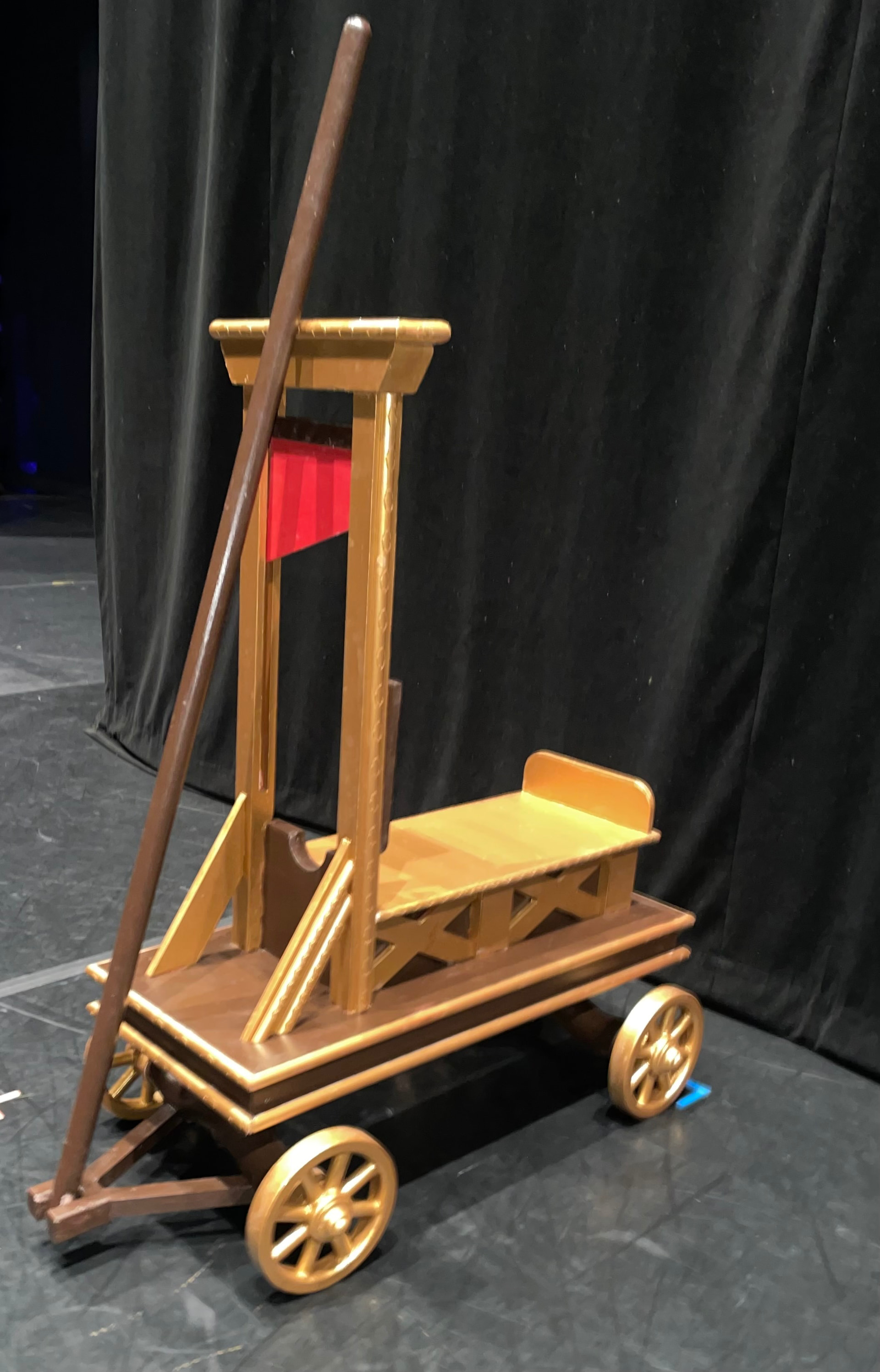
This guillotine-wagon that the ballet commissioned me to make was probably 75% cut on the CNCs. This had a lot of interconnected parts of various sizes. A lot of the fully 3D shapes were cut in two halves that were glued together.

My biggest challenge was reliable material holding for smaller parts, especially when their outside perimeter was cut out completely on the CNC. The tape-glue-accelerator method was frequently the only reliable option, but that became expensive quickly.

Most of this was done in VCarve, but it lacked one feature I needed for some small detail work on the trim. I tried that in Fusion, but exporting to STL to load into VCarve was very cumbersome, so I need to learn how to generate gcode for our CNCs directly from Fusion. I didn’t have time for that while completing the project.

1 Like

Thank you Aneel—this makes much more sense to me now, and the example is really helpful.

I shared your experince to all my team. The idea of creating a local coordinate system is especially interesting, and gives us something much more concrete to think about.

Thanks again for taking the time to explain it so clearly—and also for being understanding about my earlier reply. I’d be happy to stay in touch and update our process or ideas sometimes.

1 Like

Thank you for sharing this. The wagon looks amazing, and it’s really helpful to see a project, the photo makes the scale and complexity of the project.

The small-part holding issue is especially interesting. A few quick questions:

  • Roughly how small were the parts that became difficult to hold?

  • Would tabs, a thin uncut “onion skin,” or a reusable vacuum fixture have helped, or would they have created too much finishing work?

  • What was the specific detail or toolpath feature that VCarve could not handle?

Do you mind we set up a short call sometime so we can learn more about your workholding and software workflow?

Do you have plans for particular work-holding systems? With vacuum or tape-and-glue work-holding, getting the parts aligned to the machine is tricky, so having the CMM adapt if you’re a few degrees off would help. Of course most objects you’d measure aren’t precision machined, so even holding them in a vise doesn’t guarantee that they’re aligned to the machine axes.

1 Like

Thanks, Aneel. We haven’t finalized the workholding system yet, but we are looking at several options.
We do have a probe, and it should be possible to detect when a part is slightly rotated and create a corrected local coordinate system automatically. Making that reliable in everyday use will still require a lot of engineering and calibration.
Turning those measurements into useful CAD geometry is also a challenge. There still isn’t a simple, reliable workflow for converting or editing mesh data such as STL files, and it often requires someone with strong CAD experience. Our engineers said your examples are very valuable, and this is closely related to what they are working on now.

1 Like