Tuning on Dorian

I did some science on it and got the new tube tuned better than I’ve ever seen an HVDC-excited tube. The low end actually works!

The instructions for best layer settings are very simple, and labeled on the monitor:

  1. If you’re using <400mm/s, leave the PWM at default (1KHz), and use Min Power=0%
  2. If you’re >400mm/s, your layer will benefit from using PWM Override to 2KHz, and use Min Power=13%.

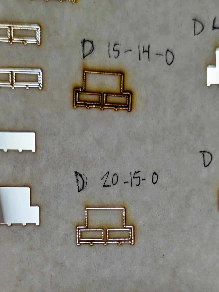
The low-speed protocol will resolve pretty small %. I was able to brown paper without cutting it, and without missing or cutting through the corners.

The beam does have some pulsation in its output, but at, say, 100mm/s with 1KHz modulation, the spatial period of the modulation is only 0.1mm, which is smaller than the beam’s focal spot.

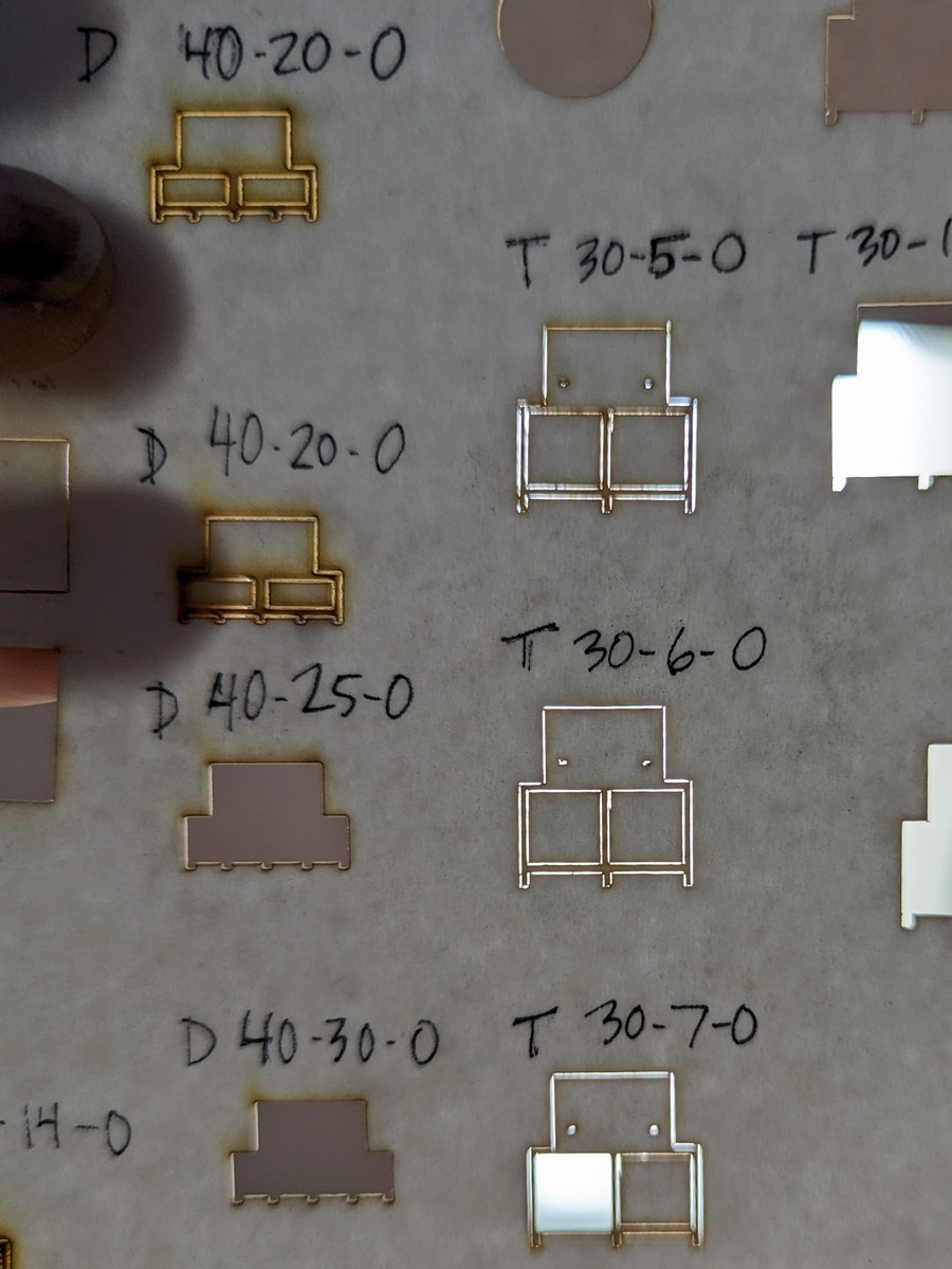
At 400mm/s, the modulation’s spatial period increases to 0.25mm, which is larger than the spot size, and in some scenarios the output modulation of the energy at 1KHz can show up on the cut. 2KHz is beyond the point where the beam’s actual output varies across a PWM period, the beam’s output is smooth. Downside, the beam output cannot be controlled on the very low end, and we need 13% for Min Power. Vector corners will very slightly overburn, but reducing to 12% means the beam will extinguish entirely on the corners.

There’s no apparent reason to use PWM Override to set modulation above 2KHz. The beam’s not going to respond faster, and it becomes worse at handling the low end.

In general, cutting all but the lightest, thinnest materials (like paper) is done at 100mm/s or less, so that falls under low speed protocol. Speeds above that are usually employed in rastering or just trying to mark, but not cut, a surface, and you may or may not go to 400mm/s.

The backlash compensation on rasters is also calibrated. It was only a 0.1mm error, but it’s offset out now,

8 Likes

Thank you for taking the time to fine tune Dorian. I know it can be time consuming. I know you probably left some people in a “WTF” moment since most people think speed and power settings when using the laser. So your information doesn’t get lost, could you please if possible, put it in a Texan country boy plain ingles? Something like in third grade maths? Like if youre using thin materials (paper, fabric, card stock, etc.) you may benefit if you stay at this power, speed, and frequency to raster/engrave or cut/vector. Or if you’re rastering/engraving, cutting/vectoring thicker stuff go to this power speed setting. If you’re feeling grand maybe explain the benefit of using “minimum power.” Something like if you want more definition or detail on your raster/engraving you may benefit by using this much minimum power or if you want crisper (not rounded) when vectoring/cutting inside corners you may want to use this much minimum power.
If people understand this information they may run the machine at the best optimal power/speeds which in turn will keep it cleaner and resulting in less maintenace and happier customers. When people understand the information, you probably would get more feed back and collaboration about sharing their speed/power settings of materials which would benefit others. Thank you again and a second gracias for optimizing Tarking. I have cut 1/2" acrylic, 1/2" pre-finished plywood, 3/4" solid Alder boards, and 1/8" plywood, all with little or no zoot on top and really no back burn in the back. All super clean cuts!

3 Likes

Fantastic news. I can hardly wait to try it out nice.

What does it mean and why does it matter? A: For a lot of jobs it will not matter. But for some special use cases it can make a big difference. Most of the time cutting plywood is just cutting plywood so you don’t need to worry about it. But when you start pushing the envelope on a machine’s capability it becomes clear that all lasers are not created equal.

Tarkin and Dorian are good examples. Dorian uses a High Voltage Direct Current -excited laser tube, Tarkin instead uses Radio Frequency and has an RF - excited laser tube (High Voltage Alternating Current). This is one of the reasons we see differences between the two lasers in performance.

One instance when this happens is the need for more precise control on power output. A good example appears during a cut when the laser head is moving towards a corner. Head movement has to slow down and briefly stop before it can accelerate in a new direction. The controller has to throttle the laser output power or else the material will be blown out near the corner. Tarkin’s tube can throttle down but Dorian’s tube has traditionally stopped lazing around 20%, before the laser head has reached the corner of the cut. So we say ‘Dorian has no low end.’ But this fact doesn’t make a difference most of the time.

I’m not a raster / fill guy so I have no experience there. But I like to cut all the things and use the lasers for mostly quick prototyping and engineering during a build. I have some material that is heavier than paper but lighter than most card stock. While trying to cut fine details in very light material tube type limitations become more apparent.

Thanks Danny

1 Like

Dorian is a laser using the cheap, common glass HVDC-excited tubes, which is driven by a flyback transformer, high voltage diode (possibly a doubler), and capacitor. This sort of supply was originally design to power old vacuum tube CRT TV anodes, which used constant DC. It has a max response of about 1millisecond, the beam can’t change must faster than that.

The other liability is that when the power is turned down with a command below 20%-10%, the beam suddenly destabilizes and extinguishes and you get no laser power output at all. Zero. You can get a 20W output from a 100W tube, but you can’t get 5W no matter what command you do.

This is important because if you’re cutting a square at 50mm/s 100% power, the machine still has to slow to a stop on the corners and accelerate in the other direction. It won’t be traveling at 50mm/s all the time. So it’s going to give way too much burn per mm there, right?

No, because the Ruida, like all controllers, auto-scales down the power based on what % of the commanded speed it’s doing. When it’s going into or coming out of a corner and doing 25mm/s actual, it reduces the command to the tube to 50%. When it’s nearing the corner and only 5mm/s, it’s commanding 5% of the tube- which, we’ve already said, will extinguish the beam. Thus the corners are uncut and the product may be useless because things don’t fall out of the stock.

Min Power is the next logical- but problematic step. It says “hey when you are coming to a stop, “zero%” command doesn’t mean zero. Let’s say 15% command is the new zero. So when you’re doing squares, 100% power on the straightaways, then go down as far as 15% command when you corner, that’s actually more than we want and the corner gets overburned, but if we go to 10% there’s zero beam and the corner is uncut and we can’t use the product. So pick your poison. We have to overburn or get no beam”. Well, the low-end performance at 1KHz is pretty good and if you follow thes numbers we can get the beam pretty low so when it’s going slow through the corners it’s not overburning or underburning.

Bottom line is to follow the above rules literally. All the materials you asked about are going to be cut at less than 400mm/s so it’s low-speed protocol. So set your Max Power to 100%, Min Power to 0%, leave PWM override unchecked on the second page.

Start with a WAG for speed, do a 20mmx20mm test square. If it cuts, try increasing your speed. If it doesn’t, decrease your speed. Until you home in on what gets your job done but in the least time.

In general, for a specific material you already have a setting for, if it’s double the thickness, slow the Speed down by half… plus a little slower than that.

If you want to engrave fills- specifically fills- then you might exceed 400mm/s, if you’re using 100% power which is likely the case, you don’t need to set Override PWM or Min Power. They won’t be used. They’ll only be used if you ask for <100% power.

I’m not sure why you’d even do a Fill at <100% power at only 400mm/s. Like 50% power @400mm/s is basically equivalent to 100% power @ 800mm/s, but the latter runs much faster.

Likewise, there’s not actually a strong case to ask for etching light vector graphics at greater than even 100 mm/s. The head will only reach that speed in the middle of a long straightaway. I want to measure that next, but I’d say like 4" min. The vast majority of the design is going to be acceleration-limited and, depending on the size and geometry of your detail, the job may only be running an average of like 50 mm/s.

2 Likes

Anyone else want to watch Real Genius after this? I’ll bring the unpopped popcorn.

1 Like

I literally have an “I (heart) Toxic Waste” T-shirt

“Rue the day”??? Who talks like that?

2 Likes

When working with very light material it’s helpful to test the cutting performance at sub optimal power. The pieces also remain intact for inspection. Dorian still stops lazing at 13 or 14%. But a test cut at 15% shows improved power control near the corners. From here you can tweak the speed or power to get the final set point for your job.


Dorian 20mm\s, 15% power, 0% min.power.


A little more power and the pieces easily detach.


Tarkin’s performance on the same material shows a smaller kerf.


With a coat of white paint it’s diorama time!
The supports are 0.025" wide and spaced 1/4" apart.

I Heart Frogs

2 Likes

Since “low end” was mentioned here, maybe it’s the right place to ask for suggestions on something I abandoned a while back:

I’m using chipboard to make molds for casting coins out of pewter – the chipboard is remarkably resilient and able the casting can pick up quite a bit of detail. Here is the three part “sandwich-style” mold of a Simpsons gag:

And here is what the pewter coins ended up looking like:

https://i.imgur.com/9G19n2J.mp4

All of this was done on Tarkin, going about 0.5mm deep into the chipboard.

I then decided to change up the design and turn the line art into raised surfaces (to better mimic actual coins) which means changing the design to feature more filled areas. Once I did that, I ran into two problems:

  1. Tarkin really didn’t like running at very low power for fill and didn’t produce a consistent result.
  2. Even when I got a good depth on the fill, the “bottom” of the fill was very uneven, producing a rough surface. Once pewter is cast, it would pick up the rough texture and reproduce it on the coin. I’ve tried varying speed/power/pass count, but would usually go back to issue #1.

Given all that: am I better off switching to Dorian (or one of the smaller lasers) for this purpose, precisely because of the low end? It seems like using Tarkin for this is total overkill.

2 Likes

Clever idea, I really like the reeded edge.

I think one the issues you are seeing is the inconsistency of the paper in the chipboard. Even if the power of the laser was perfectly consistent across the whole surface the material would still be unevenly affected. The other issue may be line vs fill…

I have tried to contour acrylic which seems like it would be a very homogenous material. I wanted to ‘trench’ a groove and create a dado joint. Think repeated line passes with a laser as needed to remove the plastic. I found the process to be somewhat inconsistent and a profile with vertical walls very difficult to achieve.

I’ve always wanted to try casting coins and what not. Got some of the equipment already. Small electric furnaces don’t have to run very long. It seems like it might be a good fit for the space.

I’m not a fill guy

1 Like

Thanks @beirdo, I think you’re right – there’s only so much consistency/smoothness one can expect from compressed pulp! :smiley: It’s a shame too, because the cost of the material and the speed with which you can iterate on designs is a huge advantage vs. making molds out of silicone or sand.

I’m not ready to completely give up on it yet, so maybe I can touch up the surfaces by hand or tumble them for a smoother finish. But I’ll put that in a separate thread.

1 Like

Tarkin is RF-excited, which is much better in every way. Its modulation can go down to 1% power if need be, and output modulation is almost 100x faster.

But chipboard is never going to have a very smooth bottom surface from laser. A CNC bit is commanded to a particular z height and that’s where it will be. Laser just delivers energy, not a specific depth, and the net cut depth will vary depending on material. Homogeneous material like acrylic will have consistent depth. Wood will cut shallower through the hard part of the grain and deeper through the soft parts.

Chipboard has no net grain, but its nature of chips and hard to cut glue will mean a rough surface due to the glue.

Since you mentioned pewter casting, maybe 3d print a model and sand cast it?

Hey Danny – thanks for the note about Tarkin.

I was hoping to avoid 3D printing + sand or silicone, mostly because of the cost/time involved, but it’s shaping up like what I’ll ultimately have to use. I’ll stick with the laser + chipboard combo to tweak the design before I start on the printing though, it seems to be good enough for that.

1 Like