Saturday 2/14: special project at Electronics Office Hours!

Hey folks! Next Saturday, 2/14, we’ll have a special project going on during our monthly office hours in the lab: we’re putting together a Home Assistant-connected temperature monitor to help keep an eye on the health of the AC units in the woodshop.

No experience required — everyone’s welcome to join, contribute, or just watch and learn. See you there!

4 Likes

Do you already have a sensor? I have spare BME/BMP280 if that works for your needs

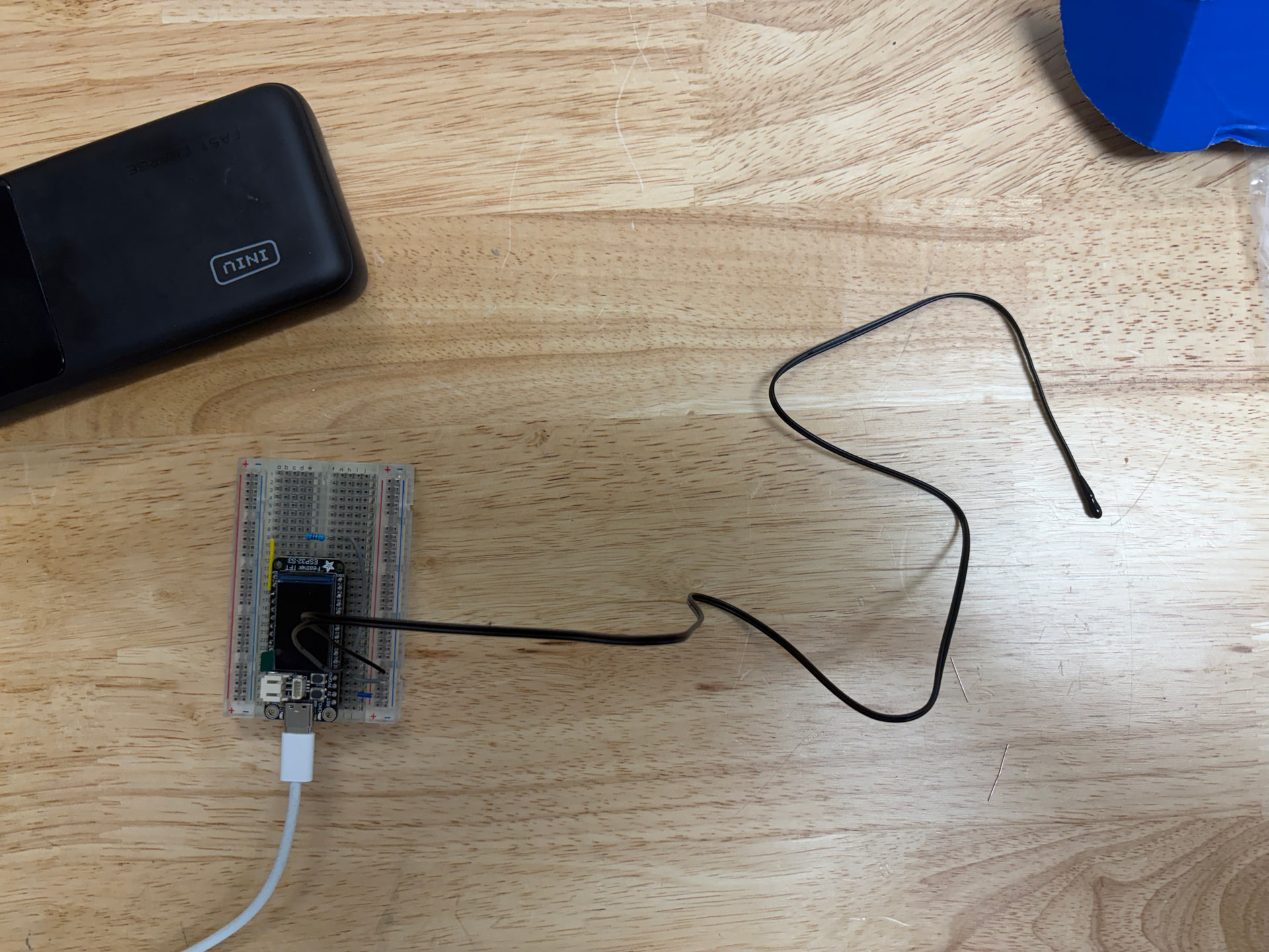
Much appreciated. We ordered a couple different thermistors since we’re trying to measure the temperature of the condenser, not necessarily the air around the unit.

Protecting the temperature control of the shop, that’s a true act of love right there :heart:

4 Likes

Sounds fun! I’ll be there and bring a few examples of microcontroller sensor data displays I’ve made.

1 Like

@JohnWickham and @aneel are great woth electronics! I encourage everyone to swing by if you have the time, I’m confident it’ll be worth the trip.

1 Like

This project got to the prototype phase pretty quickly…

@JohnWickham whipped up a quick circuit with a Feather dev board, a thermistor, a resistor, and a few wires, and we were off to the races.

We got this working using ESPHome and are collecting some data while we investigate exactly where it’s going and how we’re going to power it while it’s there (we’re not excited to climb a ladder every time the batteries need to be changed).

We used the ESPHome wizard to generate a basic YAML template…

# Set up python virtual environment in the directory named venv
 /opt/homebrew/bin/python3.13 -m venv venv # or just python -m venv venv
 source venv/bin/activate.fish # choose the activate for your shell
 pip install wheel esphome

 # Set up the yaml
 esphome wizard asmbly-hvac.yaml
 name: hvac0
 microcontroller: esp32
 board: adafruit_feather_esp32s3_tft
 wifi: Asmbly

Since we were using an NTC thermistor, there was an component pre-defined: NTC Sensor - ESPHome - Smart Home Made Simple and we confirmed that the resistor in the sample was the other side of the voltage divider here: Resistance Sensor - ESPHome - Smart Home Made Simple

Our biggest problem was that we kept getting a constant, unreasonable result out of the device. It said the voltage at the input pin was 0.98V, when we were measuring it at 1.7V. We debugged by simplifying the circuit and testing each part separately, and everything looked good. We were stumped until @Kenneth realized that the default Analog to Digital conversion on this board expects a value between 0 and 1 volts. We added an attenuation configuration and suddenly we were getting values in the right range.

Here’s our finished code:

esphome:
  name: hvac0

esp32:
  board: adafruit_feather_esp32s3_tft
  framework:
    type: esp-idf

# Enable logging
logger:

# Enable Home Assistant API
api:

ota:
  - platform: esphome
    password: ""

wifi:
  ssid: !secret wifi_ssid
  password: !secret wifi_password

sensor:
  - platform: ntc
    sensor: resistance_sensor
    calibration:
      b_constant: 3950
      reference_temperature: 25°C
      reference_resistance: 10kOhm
    name: NTC Temperature

  # source sensors:
  - platform: resistance
    id: resistance_sensor
    sensor: source_sensor
    configuration: DOWNSTREAM
    resistor: 10kOhm
    name: Resistance Sensor
  - platform: adc
    id: source_sensor
    pin: A1
    attenuation: auto
    update_interval: never

switch:
  - platform: gpio
    pin: GPIO5
    id: ntc_vcc

interval:
  - interval: 60s
    then:
      - switch.turn_on: ntc_vcc
      - component.update: source_sensor
      - switch.turn_off: ntc_vcc

Remaining to do: figure out exactly where these are going and how they’re being attached, and then whipping up an enclosure.

3 Likes

Awesome write up. Sorry I couldn’t be there to watch along, as I wouldn’t have been much help for the code.

I’m happy to help with the install and ladder portions!

2 Likes

One minor issue is powering the ESPHome device, it can be battery powered but we’d be looking at weeks or months between charges and need to keep the screen off.

A standard 120v plug near the unit it’s being installed on would let us use a common usb power brick. I can model up an enclosure once we’ve got a spot picked out, something that keeps the screen visible and the buttons usable.

Honestly, once we have the functionality nailed down, I think we should swap the dev board for one without a screen. Esphome lets us do over-the-air upgrades and watch the logs remotely. I’d rather use a display unit on the ground than try to look at the display and press the buttons while on a ladder. @JohnWickham suggested a base station, which we could put somewhere convenient

If the 24VAC power source from the thermostat system is available near by you could use one of these to get 3.3v or 5V supply from that.

https://www.amazon.com/UMLIFE-Converter-2-5-35V-Regulator-Adjustable/dp/B094ZTG5S8/?_encoding=UTF8&pd_rd_w=eAmc4&content-id=amzn1.sym.4efc43db-939e-4a80-abaf-50c6a6b8c631%3Aamzn1.symc.5a16118f-86f0-44cd-8e3e-6c5f82df43d0&pf_rd_p=4efc43db-939e-4a80-abaf-50c6a6b8c631&pf_rd_r=MJA17FWTSNG4GSAPS7EF&pd_rd_wg=QDRuh&pd_rd_r=6ea42430-39c1-42f6-8197-b67f6c34d0b2&ref_=pd_hp_d_atf_ci_mcx_mr_ca_hp_atf_d&th=1

1 Like

It was great watching and learning Saturday. Thanks for the write up and for explaining things as you went @aneel, @JohnWickham, and @Kenneth

3 Likes