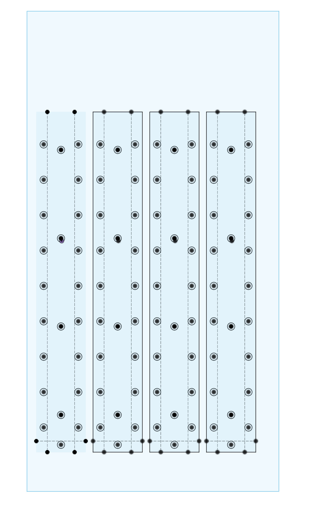
Hey all - especially @jamesfreeman - I made the model for the IQ slat with bolt holes / dog holes today… Not going to cut and level today - so thought I’d share the model in case anyone is alarmed by anything, or wants to suggest changes before I commence (this next week at some point). Did it in fusion… but exporting .stl here for others to view
Can you share a DXF of the sketch?
@jamesfreeman and I have talked about having a file like this where the machine home is 0,0.
Cutting the dog holes with the slats bolted down and the machine home as 0,0 should make jigging and operating more predictable.
How did you come to the spacing values that you used? The .3df file didn’t preserve any variable names 67mm, 96mm? One piece of feedback I have on those is that the spacing of the holes is 94mm in the X direction and 96mm in the Y direction. That’s close enough that I would assume they’re square and that might lead to a mistake.
Thanks for looking at the model. That is good feedback. 96mm Y was chosen to stay in parity with the dog holes on the tables throughout the shop…. 94mm X is just how it turned out when i made them equidistant from the edges of the board on both sides without thought about their distance apart…. I will make the X spacing 96mm as well.
1 Like
Standardizing to the MFT tables is a good idea. Maybe we can use this design to inform the Swift and get a standardization between CNCs. The Swift may not have a perimeter hole every 96mm but maybe the spacing can be divisible by 96.
It would be great if an L shaped jig that fits in the front left or front right of the Swift could also work on the IQ.
I’m willing to do some cutting and/or Fusion work to help get this done.
I really wouldn’t use 96 or 94. Use 100mm (recommended) or use 90mm. And make them genuinely square.
The advantage of using 100mm is that everybody who deals with metric expects to deal with base 10. The advantage of 90mm is that it has a huge number of divisors (and 2 of them fit into the sexageismal (base 60) system)…
96 is only useful because it’s 32*3. Note that factors of 5 are missing.
I suggested 96mm because that’s the Festool standard for MFT tables and accessories, and I thought the ability to mock up jigs (etc) on the MFT tables sounded useful.
Even if nobody actually does that, it feels wrong to look like an MFT hole pattern but not actually be one. If we do something different, I think it should be noticeably different.
I’m a little irked that the arcflat table is 5/8” holes on 2” centers, but that can be explained by metalworkers not believing in millimeters or something like that. On the bright side, it discourages migration of dogs and clamps between wood and metal work areas.
Discussion about why 32mm system:
https://www.festoolownersgroup.com/ask-festool/96-mm-mft-hole-spacing/
Thank you everyone for working on this and suggesting solutions. One thing to keep in mind with the doghole design, we don’t want to have an excessive amount of holes in the spoilboard. Using the tape and glue method for hold down is popular on the IQ, and adding to many holes really diminishes that ability. I think we should start with the holes around the exterior of the bed, similar to the Swift, and then cutting the pocket holes for the hold down bolts at the same size as well, effectively turning them into dogholes as well. This would cover the majority of the bed and give multiple options. We could design this all off the machine 0,0 so that adding it to files would be the same process as the Swift.
Thoughts?
2 Likes
That sounds fine by me. I only use the external ones, myself.