Pi standoff/power rails -pcb design

I was board today and while working on a project I decided I really needed a custom pcb to help make power management for a project easier.

For years I’ve been meaning to learn how to design pcbs but always found it a bit daunting and never really gave it a shot.

Came across this tutorial series on youtube for KiCad. Nothing to ground breaking, but it helped walk me through the whole process up through and ordering an actual board.

-> https://youtube.com/playlist?list=PL3bNyZYHcRSUhUXUt51W6nKvxx2ORvUQB

Took a couple hours to go through the whole process but it wasnt to bad once you knew what you were doing.

My project is to have a stack of various model Pi’s using standoffs, and using a custom pcb be able to direct power that is distributed through the standoffs to power the pi. (I get it’s not really a proper application, more just investigating if it would be practical.)

I have about a dozen pi’s I would want to power. I can get a 5V/40Amp power supply. Connect the positive to one rail of standoffs and the ground to another rail of standoffs.

Like the standoffs used here ->

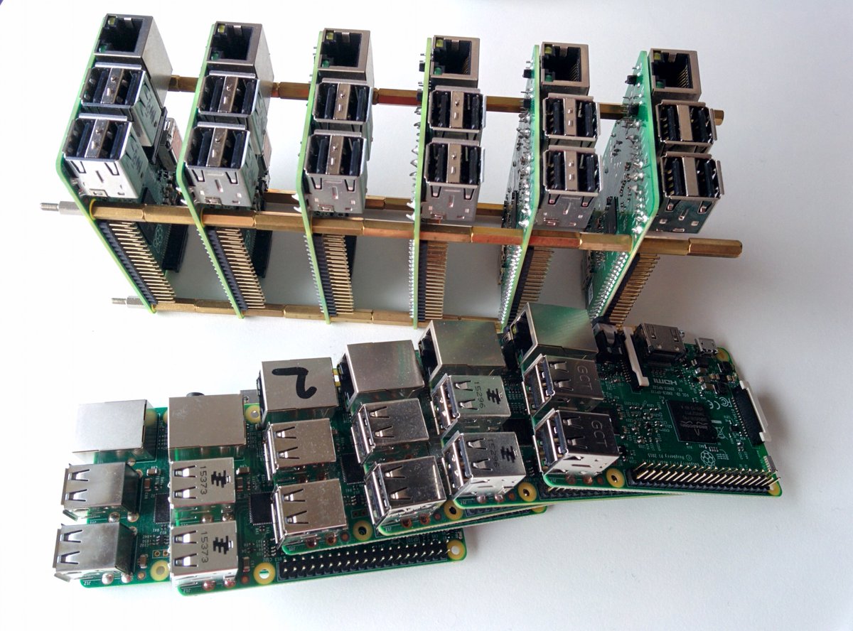
Not sure if there is a blatant reason not to do this I’m not aware of.(other than essentially exposed bus bars, but I could opt to wrap them in shrink wrap as part of the setup.)

The board has a fuse for the individual board, an idiot light incase the fuse blows, and a rgb led you could control for special purposes.

(Its my first pcb design go easy on me lol)

1 Like

@Tookys cool, I haven’t done this before either but it sounds a lot better than tracking down an outlet and managing all of those power cords.

Interesting! I’ve also been looking for ways to manage power supply for multiple RPi computers.

I was thinking a Pi equivalent of a PDU; similar to what data centers use, but much less powerful. But the stand-off idea seems much more inventive.

Did you rule out continuity between the standoffs? I don’t know about the pi specifically, but it’s not unheard-of to ground standoff holes to the same plane as things like the USB shield. If I have time this morning to find my pi I’ll check it out…

Havent ruled it out yet. If I recall the areas around the standoffs are clear of any traces but that is something I’ll wanna double check.

Also I’m not sure how much amperage the standoffs could handle. If applying 5v to the rails directly you could have 40 amps going through if powering a dozen pi’s.

I could add a DC-DC buck converter so I could use 24v @ 8.3 amp instead but then every pi would have to have a power converter which could get expensive.

would you be running all of them flat-out with USB devices concurrently? The typical power consumption should be a lot less than the “recommended supply” rating.

I agree 40A is a lot but I don’t think you’d need that very often. The standoffs are pretty stout, and you could use two each for power and ground.

Standoffs are a conductor, but honestly you’re just asking for a lot of trouble using them for anything but non-current-bearing frame ground. The revisions of RPI I’ve seen don’t have copper plating on the mounting hole, but PCB design methodology generally holds that plating the hole with either no-connect or ground plane is the same thing as nonconductive.

That is, a later rev could be dimensionally identical and plate that hole to ground and it would probably still be labeled and sold as the same thing. If a mfg error accidentally let copper ground plane into that hole area, it might be allowable.

The standoffs are brass (or bronze). This is higher resistance than pure copper. Mating one through another has limited and inconsistent contact area across the threads, and the mating force is notoriously inconsistent on any system with right-hand-threads on both ends. So, for multiple reasons, the resistance at the interface has no guarantee of being low or even consistent.

Plus, you already see that it’s creating an exposed + power busbar, with high current capacity, and you can see the problem of just leaving that out. So, non-current-bearing frame gnd only for “good practice”.

High current 24V buck converters aren’t expensive at all.

Yeah, i get they arent the ideal. But Im trying to find a cheap and clean solution for powering a bakers dozen of pi’s. Perhaps adding some kind of conductive paste into the threads to help improve current pass through?

I did go ahead and order a 24v dc -dc buck converter thinking it’d be an issue.
-> https://www.amazon.com/gp/product/B08JZ5FVLC/ref=ppx_yo_dt_b_asin_title_o03_s00?ie=UTF8&psc=1

something cheap i could just add onto a custom board if needed.

The question still is how much current / voltage could be reliably transmitted through stand offs. They aren’t ideal and it is a special case. could 24V @ 8 amp be a reliable power to transmit through them? or would it be better to go 48v @ 4 amp to try and get it as low as possible.

I have been looking at POE options, but they are a bit expensive per board, and not every pi i have has POE as an option.

Passive POE may be a viable option, but still isnt an ideal, and on the Pi2 or older board id have to splice in a custom ethernet cable.
-> https://www.electronics-lab.com/project/60v-5v-dc-dc-step-converter-using-lmr16030/

Active POE would be cool, came across one option on digikey where they have active POE with a auxiliary power option so you could choose a power source, but the POE IC chip alone is $7 not counting the PCB and other components.
-> https://www.analog.com/media/en/technical-documentation/data-sheets/4278fc.pdf

They have POE hats you can buy for the pi for $20 each, but they dont support a passive power source, so you’d have to buy a $200 router to have POE in it.

If I could get away with a passive injector module and use a poe hat it wouldn’t be to bad.

The current solution I’ve come up with was a bulk usb charge station with 60 amps worth of power. But still a lot of cables to contend with.

RPi’s are notorious for requiring a remarkable amount current and get kind of snotty if the supply isn’t fairly quiet, too.

IIRC, the CanaKit USB supplies are almost 3A at 5V. That’s 36A and the RPi’s don’t like that being noisy–which is almost certain to be true for a long run of 5V like this.

If you’re designing a board anyway, you can put something like an LM22670 at each RPi power supply so you can Buck regulate down from 24V. (About 5$ for the 5V fixed version of the chip and 2$ per inductor plus some popcorn parts). That’s likely to be much more stable.

I just did some looking up and was suprised when i saw that the raspberry pi website says the supplies actually need to be 5.1V (not just 5.0)
image

The do still function down to 4.63v
image

So I’m thinking to run 24v on the standoff rails, and using a buck converter set to 5.1V for each pi.

OR should I just plan to hard wire the boards using 18 awg and daisy chain them? (with enough slack so they can be removed from a mounted board) still with 24 volt and a buck converter each?

[edit]
So looking at it, trying to run 12 pi’s with 5V(42A assuming max power just to be sure) directly would require gauge 4 wire, which is over 0.2" in diameter, so i think needing such a heavy gauge is a red flag I’m doing something very wrong.

If using a 24v(9A assuming max power and conversion loss) We would only need 18 gauge wire which is only 0.04" in diameter.

Looking at the thread area of the 2.5mm thread standoff, if we have a full revolution of engagement (which you typically assume 3 threads worth of engagement in mechanical calculations) on the 2.5mm thread of the stand offs it would be the equivalent of a 16 gauge wire about a 0.0508 diameter. So as long as a spring washer is used to keep the threads engaged it probably wouldn’t be to bad of a connection.

Although I can find spring washers that would theoretically work. I don’t trust that they will apply enough force to keep the engagement i want, and to prevent the stand offs from slipping.

So ill go ahead and plan on using 24v and using wires instead of the standoffs. I agree with Danny, it would theoretically work, and is doable, but it may not be compatible with future pi’s, and may become a problem with either noise on the lines, unreliable signals, inconsistent conduction through the threads, and an exposed bus bar hazard.

If anybody is interested in a group buy on the boards let me know. I’ll plan to make 15 boards of whatever i design for myself. I’ll go ahead and start working on a new board design tonight. Also if anybody has more experince in board design that would like to collab as well let me know. This is my first board design project.