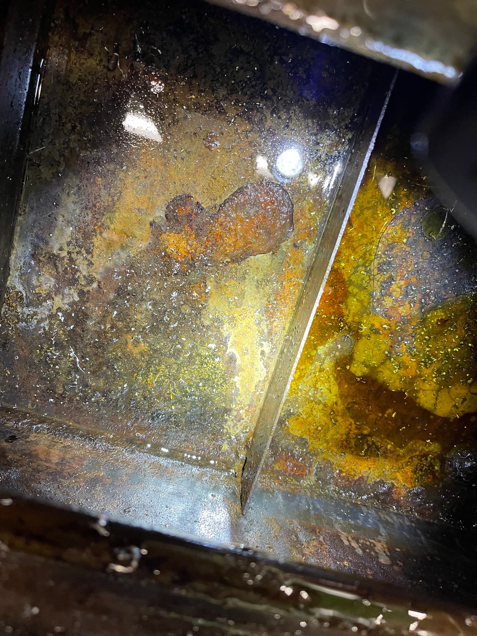
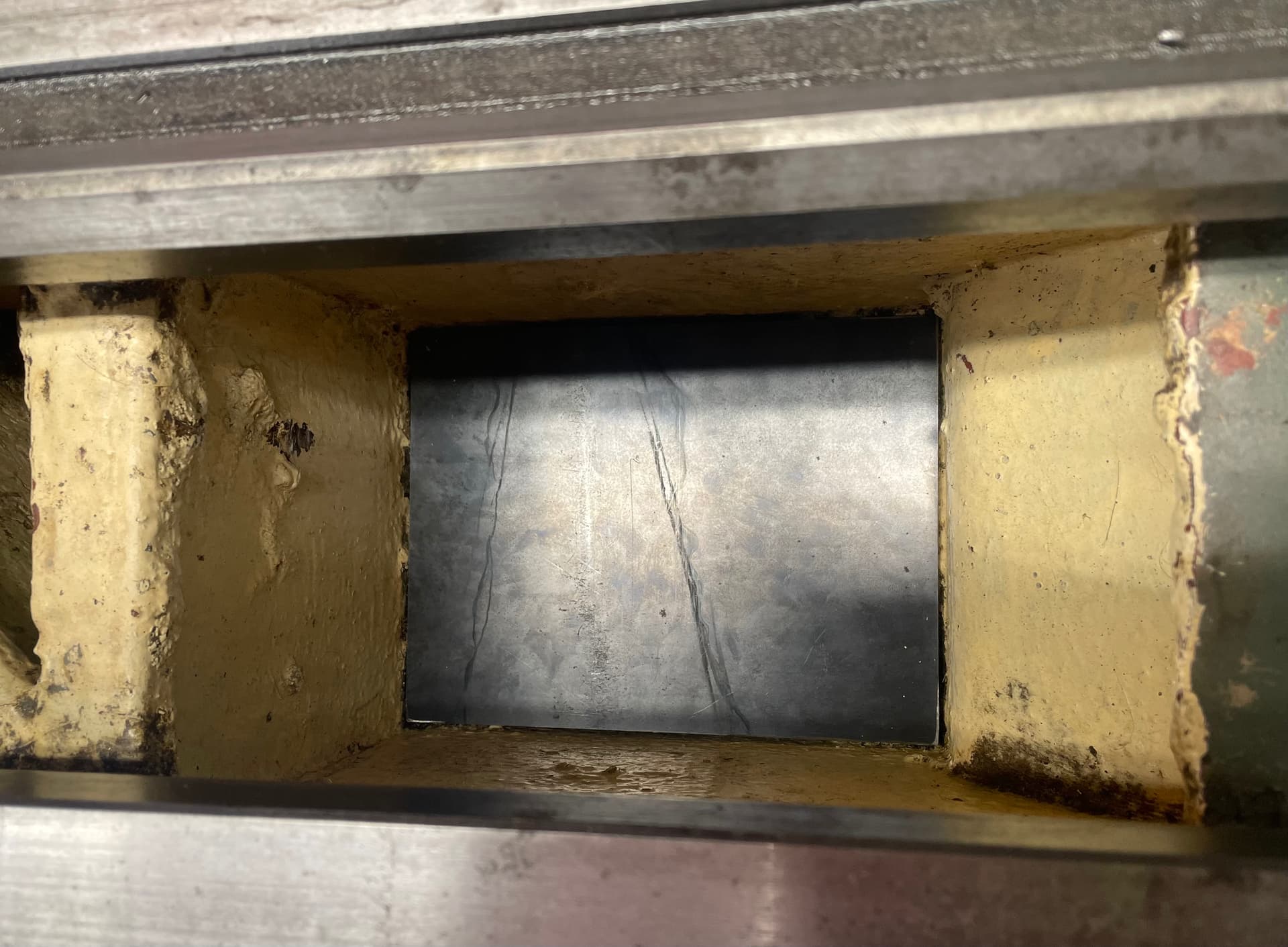
I looked at the drain in the trough. There is a hole in side. The hose going to the pump seems fine for now. I didn’t look too hard if the reservoir is removable from the trough. I’m not against cleaning the area with the hole and putting some tar in the hole and area?
1 Like
Thank you @JoeN, I’ll be at the space later today to take some measurements and start thinking through geometry that can work. I would like to try my hand at welding some aluminum for this project but that is up to you if you’d like to share the stock. I guess Steel may be the better choice as it would add more weight to the machine and potentially dampen vibrations but still Aluminum would be nice to look at before all the steel chips scratch it.
I’ll be taking a look at the coolant system tonight as well. Can’t promise I’ll get to however, I’ll try to focus on completing the backplate first.
No worries. Thank you for working on the backplate and coolant. I’m going to look and see if the reservoir is removeable and weld/braze the hole tomorrow.
I tighented up the backlash on the crossslide. I will show everyone tomorrow.
Thank you to @mgmoore for his tireless work today. We got the cross slide and compound gibs adjusted. Cleaned pretty much every surface. Welded the holes in the reservoir (still leaking, just less). Have a solution to seal it. Check the power feed issues and determined that it needs more studying and investigation. We stopped at a good point.
Things still needing attention:
-finish machining tailstock parts
-backstop
-clean and seal reservoir
-order coolant
-bring polycarbonate shield
-install polycarbonate shield
-look at how the 3jaw is attached
-possibly make parts to mount the 4jaw
-figure out why the power feed/threading doesn’t work
-investigate a new larger quick change tool post
2 Likes
I had a few additional minor to do items I wrote down. I will address most of these at some point:
- catch plate for the left section to prevent chips and junk from falling down into the tool storage area (I rough cut a piece for this tonight and partially milled it to size; I’ll finish it sometime soon.)
- the brake spring needs adjusting or replacing
- some clearer labelling would help, primarily once we get the feed working
- organizing the tools, especially separating out the good ones
2 Likes
Yes. Thank you for the additions to the list.
1 Like
@mgmoore The polycarb shield is on the workbench. I’m looking for the base to mount it to the lathe.
1 Like
The tank sealer is on order. After welding the reservoir tank. The tank has a bunch of pin holes. The tank is also difficult to remove. I think this is the best solution. It will take several days to prep the reservoir for the sealant. I will bring some semi-synthetic coolant to mix. I will put in a purchase request for a 5 gallon bucket of coolant. It will all be used on the Rofu Fu mill.
1 Like
Hi Joe, Yesterday I took some measurements of the back of the lathe where the sheet metal backer for catching chips will go and I am in the process of designing now in Fusion 360. I wanted to ask you what the thickness of the sheet metal you have on hand is so I can design around that parameter. Also here is the plan so far for the sheetmetal backer:
-
Finish first version of design in Fusion 360 and present here to get feedback. (I’ll give a figure as to how much material the approved design will require)
-
If all involved are in agreement with the design I will then mock up a prototype using cardboard to analyze fit and function.
-
If fit and function work then I will will need to either plasma cut sheets or use an angle grinder or if anyone has access to a plasma cnc table we can have the parts cut there.
-
Weld up the parts and done.
Here are some pictures of the sheet metal backer so far. If you guys have suggestions feel free to chip in.
Front
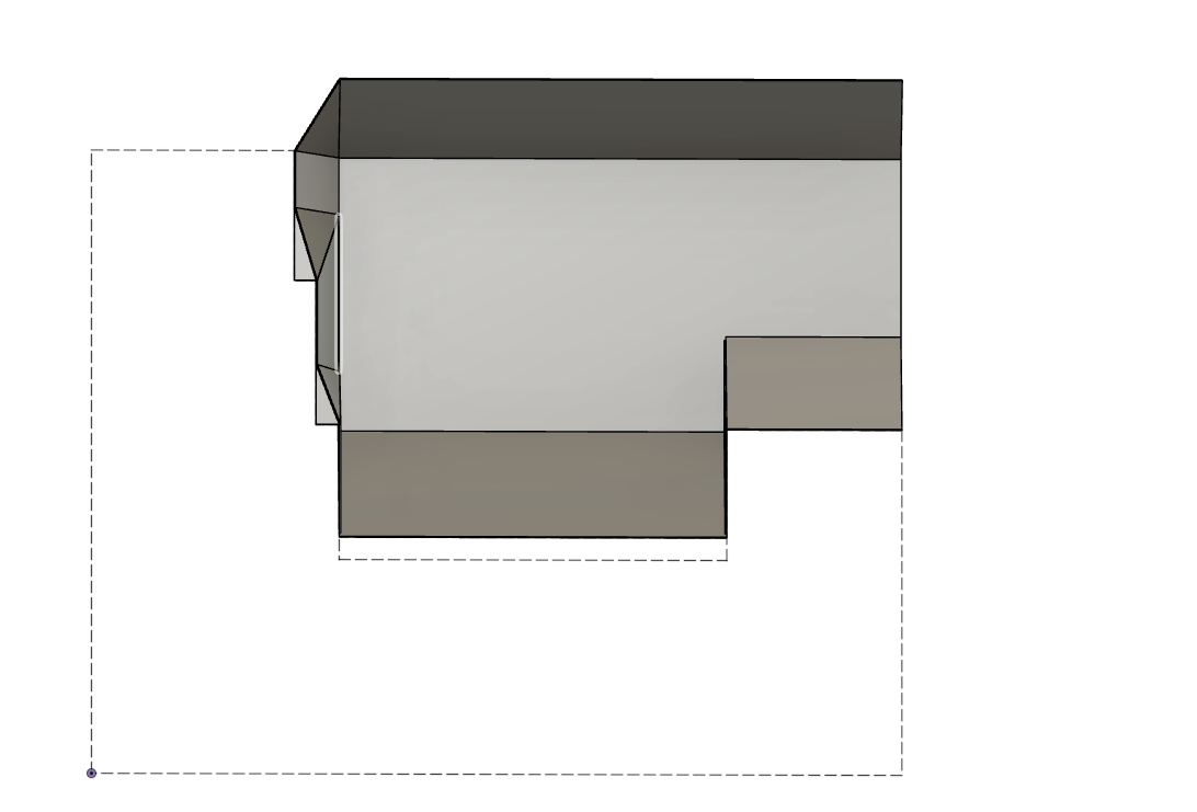
Back
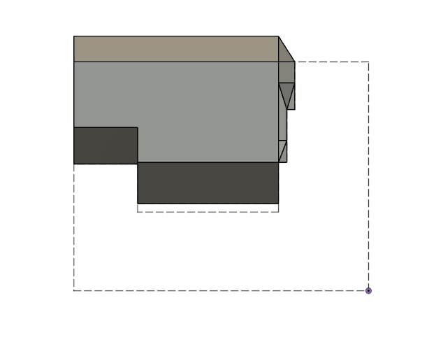
Angle 1
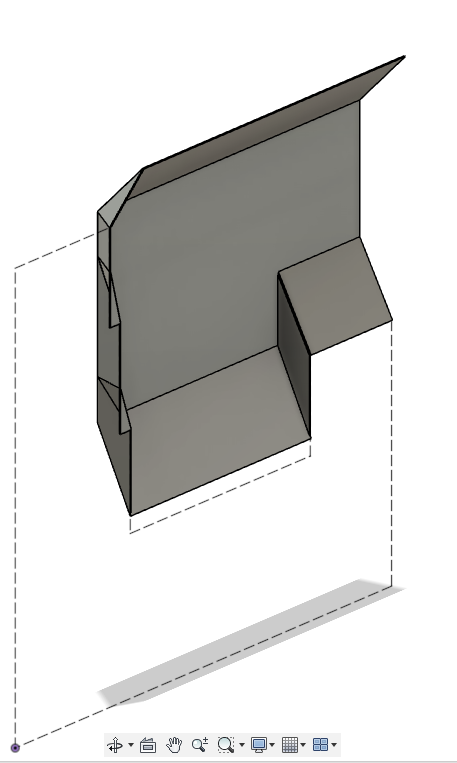
Angle 2
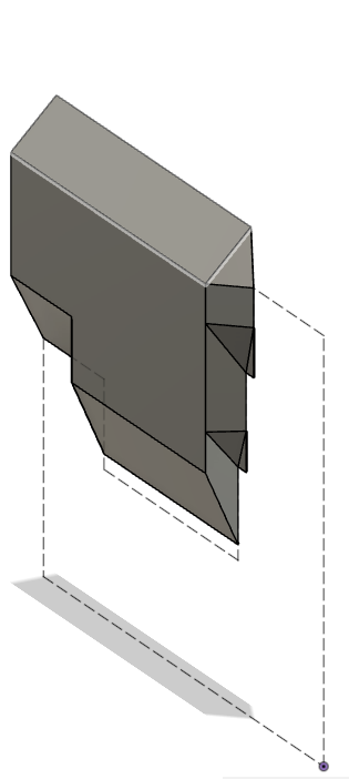
I still need to include tabs to mount to the lathe. Also the dashed lines you see in the picture are the outline of the lathe as seen from the backside. Adding up the area of each panel needed to make this current design I calculated we would need minimum one half of a 4’x8’ sheet of steel or aluminum. I would prefer to have a full sheet if possible to account for mistakes I will make during fabrication. In the mean time, next step is to make a cardboard prototype to test fit and function of this design.
@Andres79 That is super nice. The steel we have at the space is probably 14 gauge. It is 23.5" high and 8’ long. We have plenty of material. I have circular saw that cuts sheet goods.
I spent a bit of time at the space today and took the 3 jaw chuck off the lathe. I reinstalled it after wiping the mating surfaces down. Just a reminder to anyone doing something like this, always put a piece of wood below the chuck/on top of the ways, so you don’t risk damaging the ways.
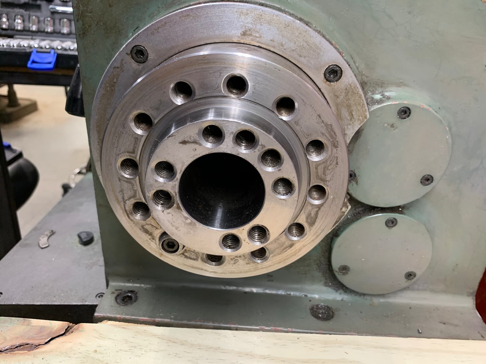
I also took a few measurements, and it seems to match up on the later diagram from the PDF… the one with the #5 M.T. So we know which nose we have.
The 4 jaw chuck has 4 bolt-holes, on ~R36.5mm. The holes are ~D12mm. The center bore is ~50mm. The bolts from the 3 jaw chuck fit in it holes perfectly (I don’t know which size bolts they are, I should have noted it), but the bolt pattern isn’t the same between the flange and the 4 jaw chuck.
So someone will need to cook up an adaptor plate between a A1-5 lathe nose to a the 4 bolt flange. I’m not that experienced, but I’d think if we can make something that’ll connect to the outer bolt ring&key on the nose, and have holes to take the bolts from the 4 jaw. I didn’t think about it at the time, but I bet the 4 jaw’s center bore is probably tapered, so it should probably mate with that.
Also, it looks like the bolts on the 3 jaw, which let you turn the jaws around, need replacement. The heads are a bit torn up, and it’s better to replace them now before they strip out. I should have gotten bolt dims, but I didn’t think about it at the time.
2 Likes
Awesome. Now we can make the taper and hole pattern. Thank you.
@mgmoore I got new screws for the mesh drain. They are installed.
1 Like
Thank you everyone for pitching in. The metal lathe has gotten some much needed maintenance. The lathe also is getting a new backstop and 4 jaw chuck.
2 Likes
If someone could use acetone to clean the chemical residue in the reservoir that would be awesome. I would get a clean chip brush and apply and let it dry.
I will come by tomorrow to treat the rust with metal prep. Once the rust treatment has dried (24 hrs). I will add the tank sealer. Then we wait another 24 hrs. We might have to replace the supply line for the coolant nozzle. It got smashed pretty hard at some point prior to coming to the space. The hose looks like a dishwasher supply line?
Let me know if you are able to get to acetone today?
I thought there were several cans of acetone in the tall cabinet by the milling machine.
I finished the plate to block off the hole above the tool storage cabinet. We might want to paint it or something to prevent rust.
I saw the shield, but I’ll definitely need to see the base before making plans. I have a feeling I should wait until @Andres79 finishes the back plate; they will certainly depend on each other. It’s possible the base can piggyback on the backplate attachment points.
1 Like
I’m fitting the coardboard mock-up today and if all goes will with the design I’ll start cutting steel tomorrow and tack welding it up.
I will bring the circular saw and leave in near the metal lathe to cut the steel when you are ready