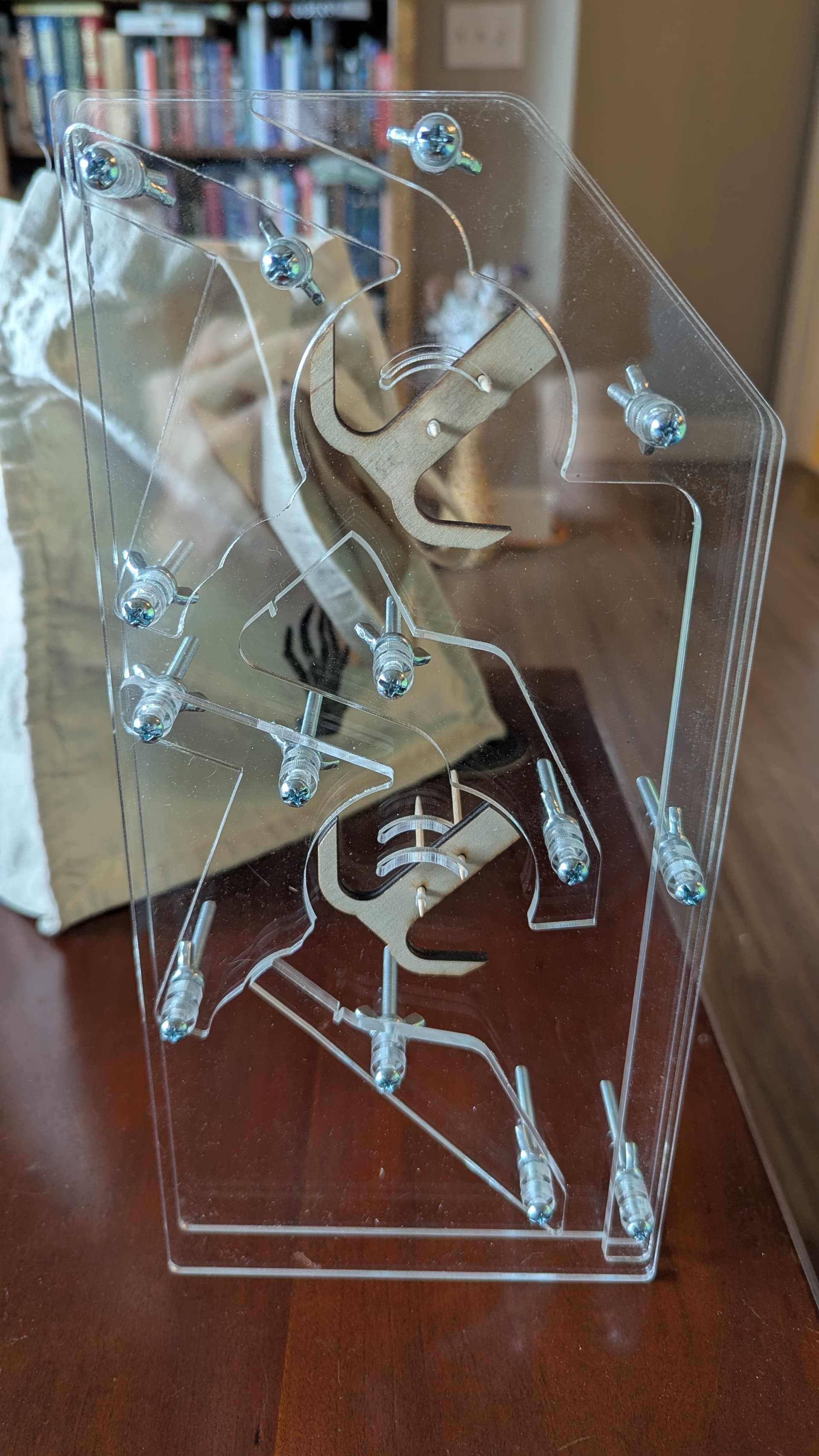
Howdy, all! A couple days ago I finally booked some time on the laser to break ground on the marble computer I’ve been designing. This is the first physical test piece, two bits of an adder.
I stumbled almost accidentally on this design with an interior “track plane” sandwiched between two big “separation planes”, and I’m really happy with both the look and how easy it is to cut and assemble.
Each of the two wood toggles is a bit, representing 0 when it points left and 1 when it points right. Putting a marble in the top track adds 1, and inserting a marble half way down the left side adds 2. When the top bit flips from 1 to 0 (right to left), the marble goes down the left side track and “carries” to the next bit, incrementing it. In a larger adder, this carry action could continue through more bits until one of them flips left to right (0 to 1). At that point, the marble falls down the exit channel on the right side and into a sink.
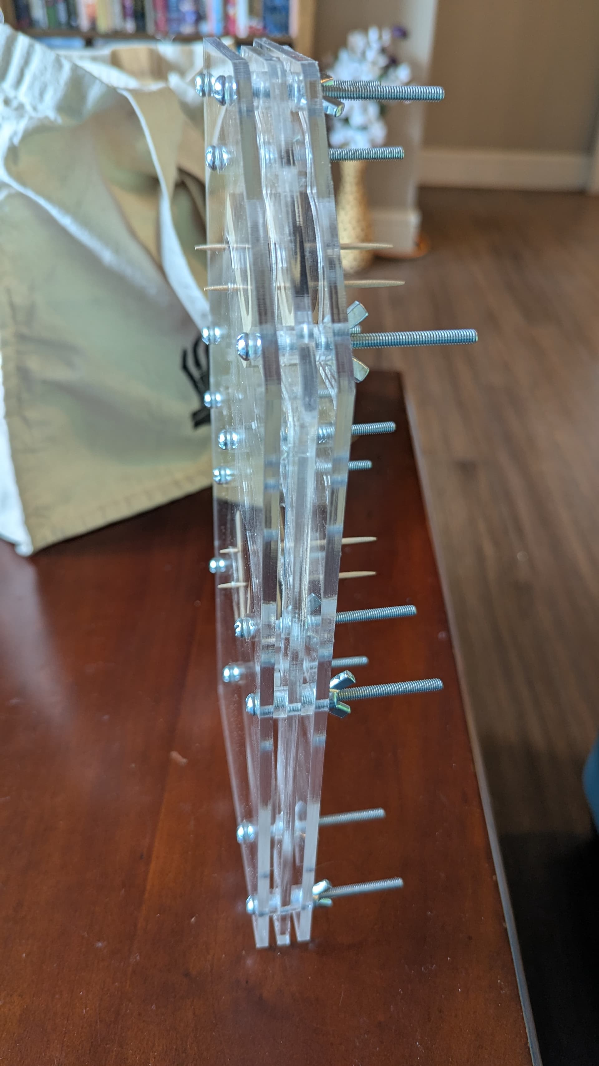
I didn’t realize this with my test cuts, but I was running the laser at a speed just slow enough to barely cut through the material. So my final cut had a few places where it didn’t quite cut through. I wasn’t careful about my origin so I had to break the acrylic a bit to get the pieces out. Luckily I don’t think that’s noticeable, and I didn’t get any cracking. Another artifact of that is that the sides of the parts are angled, since more of the plastic melted at the top than at the bottom. For those with more acrylic experience, is that a normal artifact of lasering this material, or was that just because I was cutting too fast?
The front and back planes feel much stronger than I need. I’m thinking of getting thinner acrylic for those, to help cut the weight down. Does anyone have suggestions for thicknesses which are sturdy enough to stand on their own but still thin? I’m thinking of getting 0.1 inch (half the current thickness) if I can find that.
The next test will have another track plane on the layer behind, and switches connecting between multiple planes. I’ll post further updates in this thread!
The previous gate design had some pretty big flaws:
It had very inconsistent timing. Sometimes the marble would exit immediately, other times it would linger in the gate. You can see this a bit in the above video. Timing from entering the top gate to entering the bottom gate could be anywhere from 0.5 seconds to 1.5 seconds. The computer will ultimately use timing to determine when an operation is done, so this is too much variance and the worst case is too slow.
It would sometimes engage only halfway. The gate could “bounce” after flipping and end up not fully engaged in either direction. This could lead to a jam, either in the gate itself or in other connected gates (not built yet).
To fix these issues, I designed a new gate. The new one controls the movement of the ball more, and has a sharper exit angle to push the ball out. It also uses a second embedded marble as a counterweight to prevent bouncing, and make sure the gate is always entirely engaged.
To my delight, the new gate is extremely consistent! The time from entering the top gate to entering the bottom gate is almost exactly 0.57 seconds, every time. With a small buffer, this should allow an entire addition operation to happen in around 5 seconds, which is on target for my goal of 10 seconds per instruction.
Good progress over the weekend! Most of the time the marble spends in the above design is in the out-and-back segment between the gates. I wanted to see if I could shorten it by giving the top gate a steeper exit angle. Mostly due to luck, that worked beautifully, as shown in this extremely satisfying video at 1/8th speed:
With this gate and path, the time from entering the top gate to entering the bottom gate is down to 0.36 seconds! That speed would allow for a 3-second add. Further improvements are possible, but I think this is probably at the point where it’s no longer a bottleneck.
After that, I designed the “set” gate shape. If the set gate is 0 and a marble passes through it, it becomes 1. If it is already 1, it stays 1. The marble goes right if the gate changes, and left if it stayed the same.
Here it is in action:
And that should be all the fundamental shapes we need for logic. The unset gate is made by mirroring the set gate, and the inspect gate is made by using the flat side of the set gate on both sides, to make a gate that never moves on its own. These four shapes can be attached to one axle to form a bit in the ALU, capable of the four basic operations of this computer: Toggle bits (xor/add/not/decrement), set bits (or/ones), unset bits (and_not/zero), and inspect bits (store/display).
I think that’s about all the value I can get from this prototype. The next piece to prototype is the mechanism that takes a ball from the input and moves it to the plane with the right gate shape for the current operation.
Ok, after much testing, prototype 2 is done! For this one, I wanted to pick a different part of the computer, but still using multiple layers and passing marbles between them. I also wanted to target a look closer to that of the final build. I think it turned out pretty well! Here’s a 360 shot:
This is a prototype marble decoder. It has two bits, which can be toggled separately by dropping marbles into the back plane. When a marble is dropped in the front, it can come out in any of the first four planes. The two bits select which one it will come out of. Here’s a full cycle of all four possibilities:
And that same cycle from the front:
In the final build, there will be eight of these stacked vertically, which route each bit of the input operand to the appropriate layer/operand of the ALU. The layer selection bits will be configured by the instruction.
I’ll bring this to the Laser SIG next week for anyone who wants to see it in person!
Next prototype will most likely be a few bits of instruction memory. Stay tuned!