I am designing a vertical jig for the Laguna iQ CNC machine.
Please send me the radius and coordinates for the dog holes on the Laguna iQ CNC machine. Ideally the coordinates are with respect to the hardware home position after doing the zero initialize procedure.
I will incorporate that into my prototype vertical jig so that is always registering to a known zero home if folks lock the jig in place using the dog holes.
I have not measured the distance from hardware home to the dog hole zero position yet. I keep intending to, but the work I’ve been doing on there doesn’t require it and so I keep forgetting.
I will be going up there tomorrow, I think - so if I can get it then if you aren’t going up there.
I should point out that the “right” slat (facing the machine) on the IQ does not match the model… my mistake. It works fine in terms of being a true vertical/horizontal reference for the dogs… but if you are counting on needing the right side slat dog holes for your vertical jig to be in their “ideal” positions, we should re-cut the slat. If that’s confusing, let me know and I can explain further.
Got the STEP file Doug, thanks. I assume there is one left, two center and one right spoilboard pieces for the IQ. Also is the separation between each spoilboard in the STEP file equal to the actual T-Track width - I think the spoilboard pieces in the STEP file are farther apart than the actual T-Track spacing?
You are right, Brian - the “center” slat is only in the file once, but was cut twice to go onto the machine. And you’re also right that the spacing between the slats in the file is random, with no bearing on the T-Track spacing at all. I contemplated making an assembly that combined all the components and the tracks in fusion - but got busy with other things. That still could be done.
I know that James wants to revisit the placement of the dog holes so that they track to specific locations in relation to “machine home”. I’ll sync up with him - and so there may be another version of this file coming (and another version of the slats on the machine). If I’m one to revisit it, I’ll probably add a component assembly with exact t-track spacing because I can see how it’d probably be helpful to some folks. Not 100% sure how that assembly will translate if I export it out of fusion - but I’m guessing it’ll be okay.
Please provide the X, Y coordinates of the dog holes with respect to the machine zero.
This will provide registration for the vertical jig and save folks a lot of time getting the vertical jig to work properly. It is a highly detailed operation to get to work properly.
Simple X,Y coordinates independent of whatever modeling tool you use. If you cannot just get me the darn g-code and I can figure it out.
Sorry, Christopher - I have not been up to the shop since you asked for this and am busy with some projects. I’ll be up there this next week.
At first, I thought you wanted “zero” for where the horizontal/vertical dog holes meet in relation to machine home. I now understand, I think, that you want actual hole locations in reference to home?
There is currently no relationship between machine home and the location of the dog holes and so those measurements will need to be taken manually. And I should point out, as I said in a previous message, that James wants to change it so those holes do have a relationship to home - so any work you do based on the current relationships will probably change. If, knowing this, you still want to proceed - could you possibly let me know what specific holes you need values for? Or do you actually need all the hole values? If so - that may be more time consuming than I am able to help you with.
I should add - this work was all volunteer and there were no specified requirements for dog hole / machine home relationships - And I don’t need that for my work so it was not a consideration (and I did open this work up for discussion on this forum before I started)….
I am happy to continue helping, but if the pacing of my time is too slow - anyone that wants to build on top of what I have done or start from scratch will not hurt my feelings.
I too am interested in the horizontal/vertical dog hole locations to create a simple edge milling jig which mounts into two of the front dog holes of the IQ. Since we are planning on changing the current holes to satisfy James’ request, I’ll wait until the locations of these newer ones are defined based upon the IQ home location. Doug, I appreciate your efforts and thank you for what you have done so far.
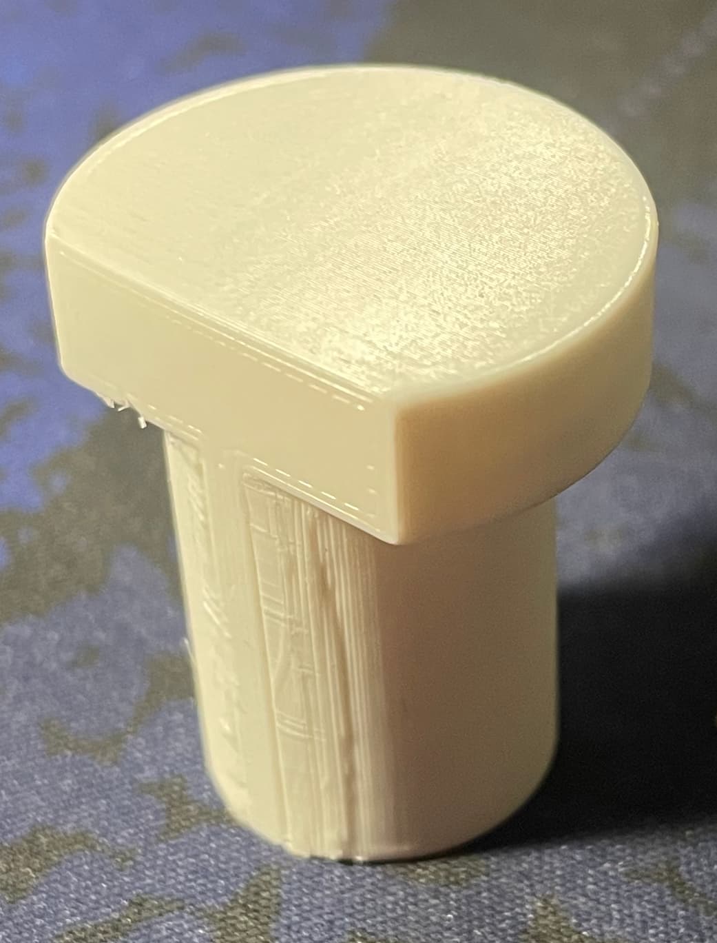
Quickly created a Bench Dog in FreeCAD and printed in PLA (sliced vertically, 0.15mm layers with 30% infill). Maybe similar to aluminum ones, but cheap, readily available, and easily adjustable design. For me it’s good enough for what I’m doing. At least if I crash into one of these it might be somewhat forgiving.
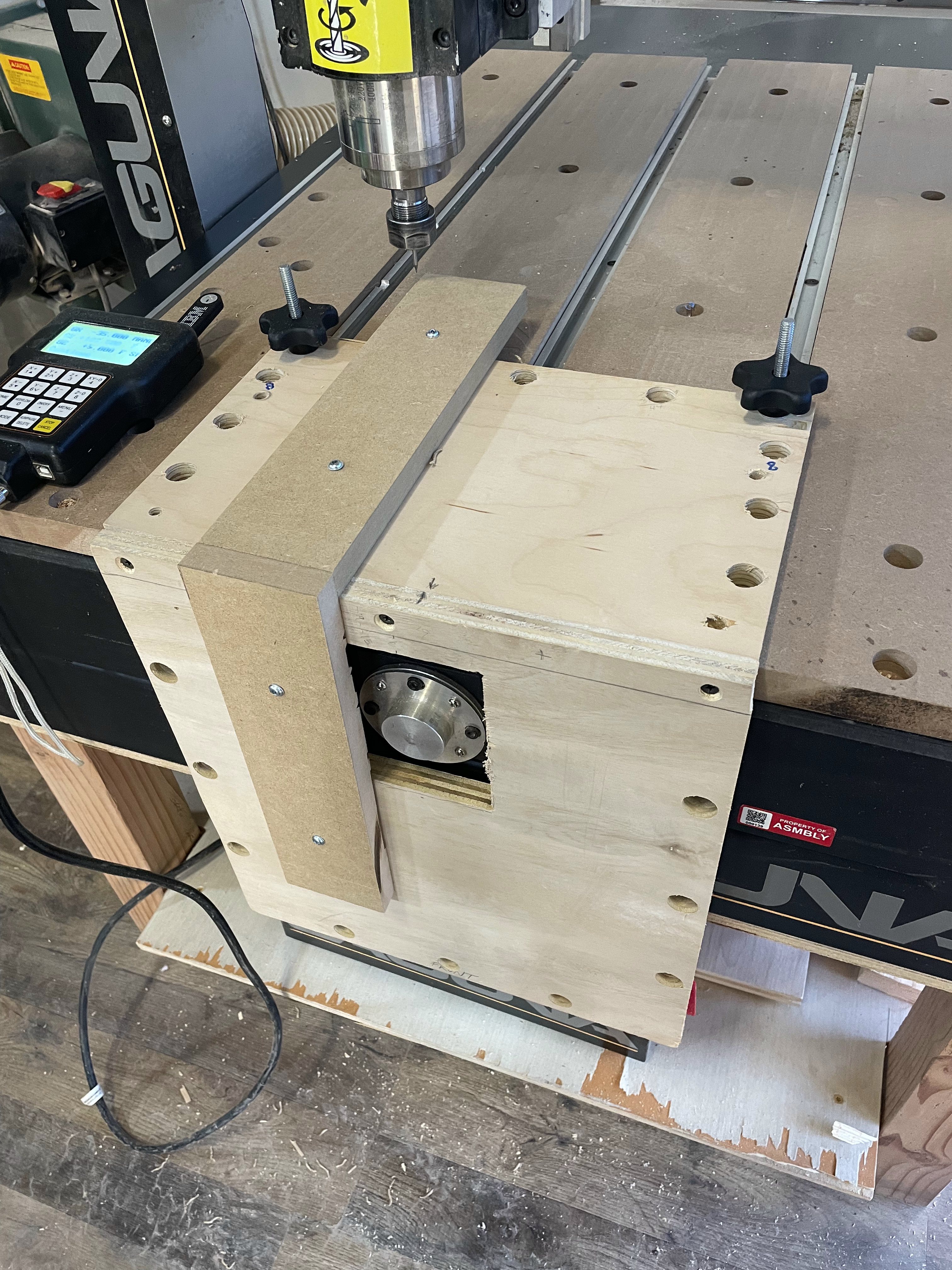
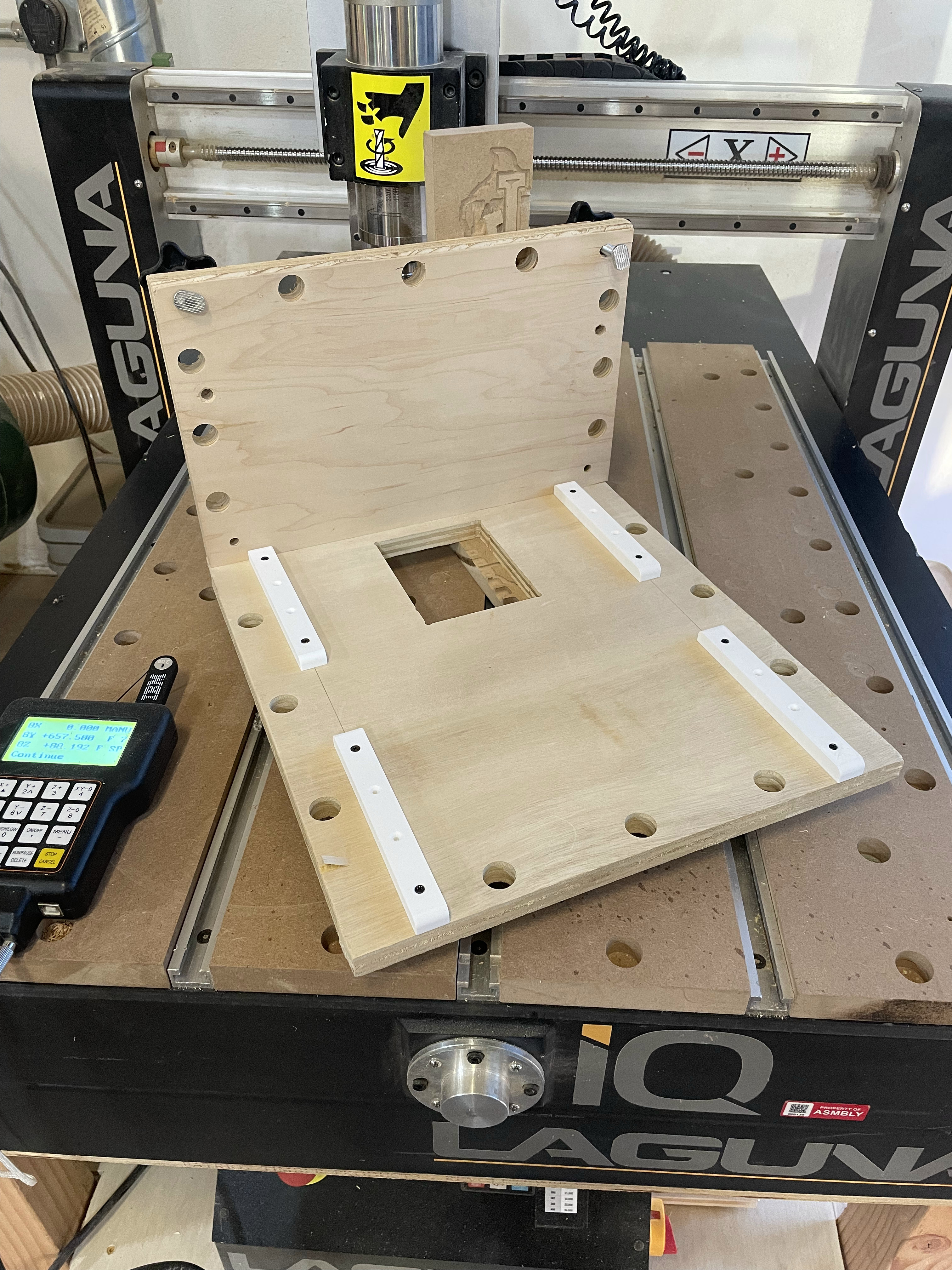
I worked on my first-pass of a simple edge jig. I used some scrap 3/4" birch plywood for it. It needs to be wider, but it’s good enough for a first pass with some 3" MDF as test pieces. Some pictures follow…
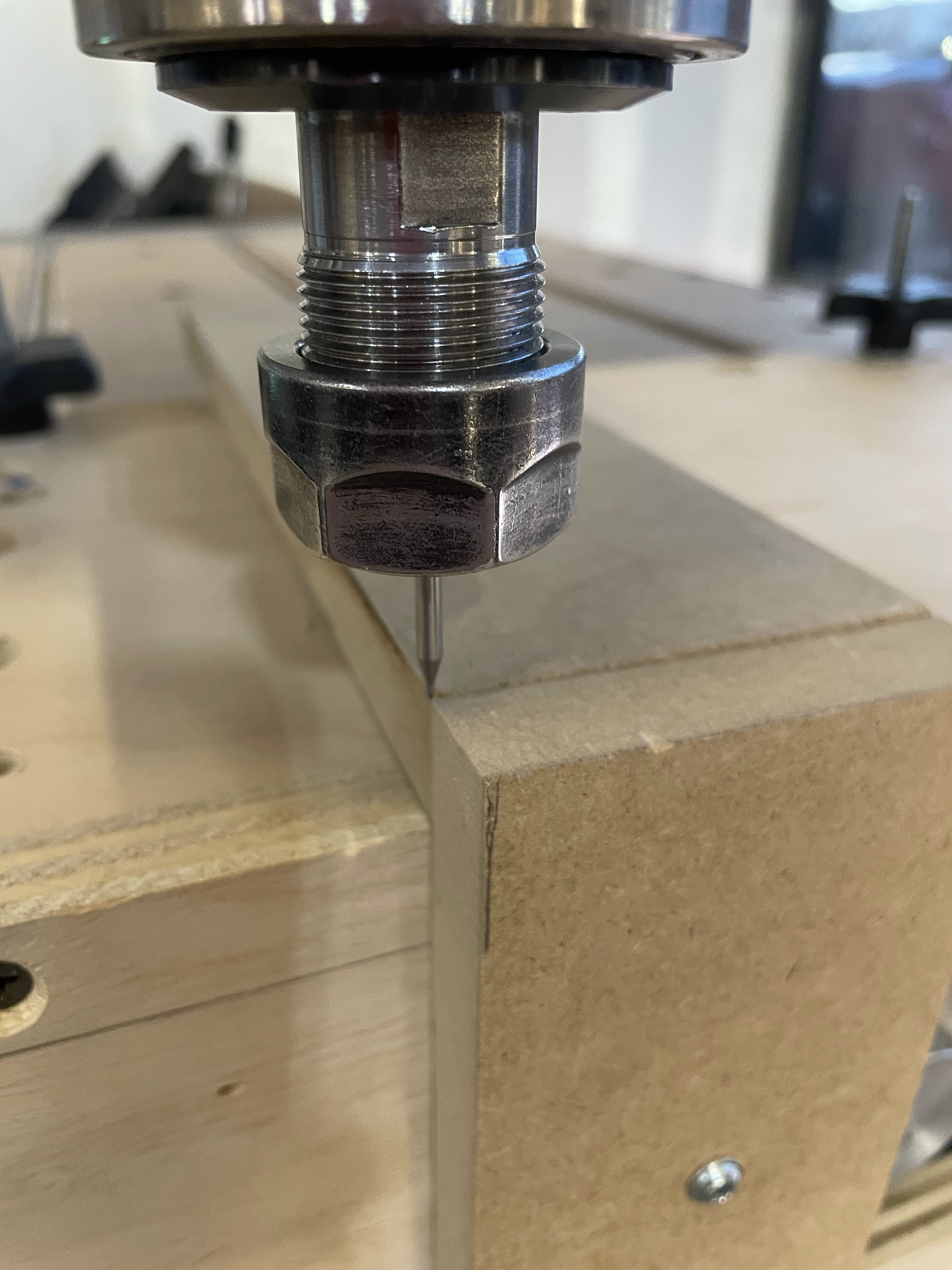
I used a pointed (engraving) tool to adjust the zero-zero at the front edge. I’ll probably need some sort of adjuster on the front panel to set its vertical angle. I don’t know if I will need the third and final adjustor to set the top planar angle.
Your work on this is very appreciated. I wouldn’t consider it to slow, as you have completed it before anyone else. With one small adjustment, we’ll have the dogholes completed and checking off all the boxes members have requested.