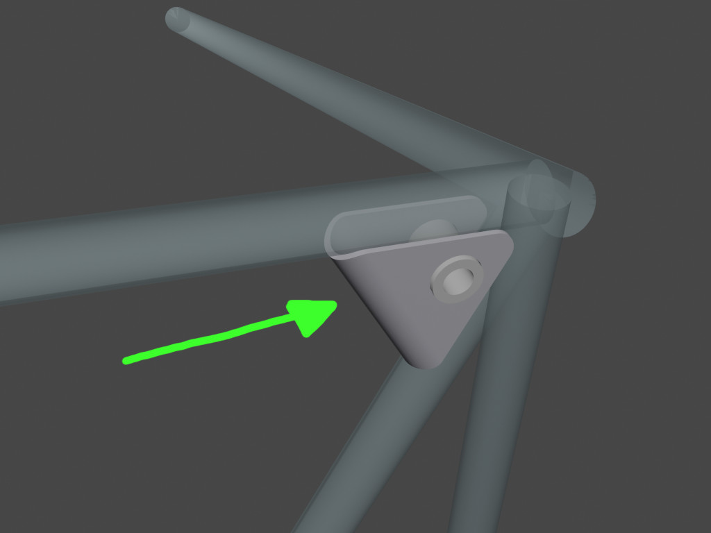
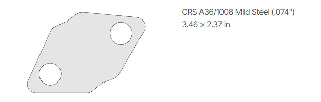
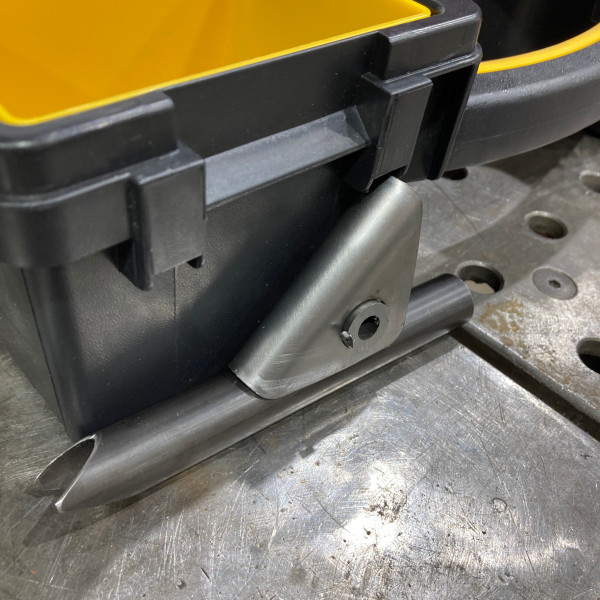
Hi, I’d like to bend these metal corner gussets to be welded. I ordered the flat sheet metal from Send Cut Send (they can’t bend them at this big radius) and I also ordered versions without the holes.
The inside diameter of the bend is about 5/8" and the outside diameter is about 3/4".
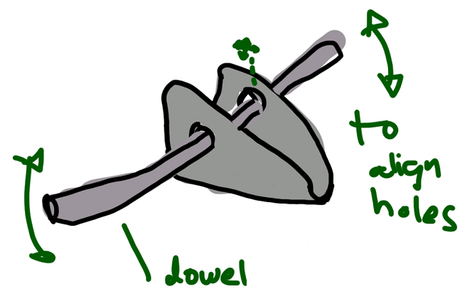
I have a separate jig for to align the dowels. The holes in the gussets are 2% oversized. It would be nice if they lined up and the bend radius was within 0.05". The rest has looser tolerances. It’s going to be welded so it won’t matter too much if they are perfect.
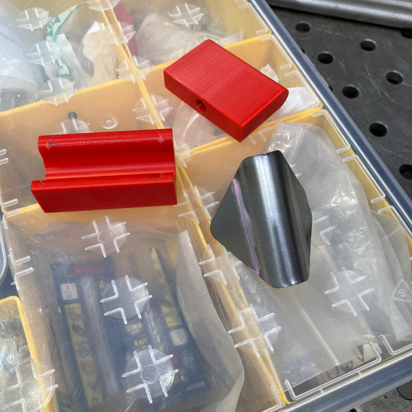
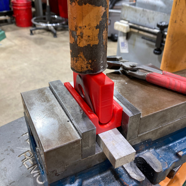
I’d recommend thinking about adding some features to your dies to locate the part and the dies relative to each other. 3D printed plastic pins turn out to snap easily, so I ended up using steel dowel pins and 3D printing holes on both sides to receive them.
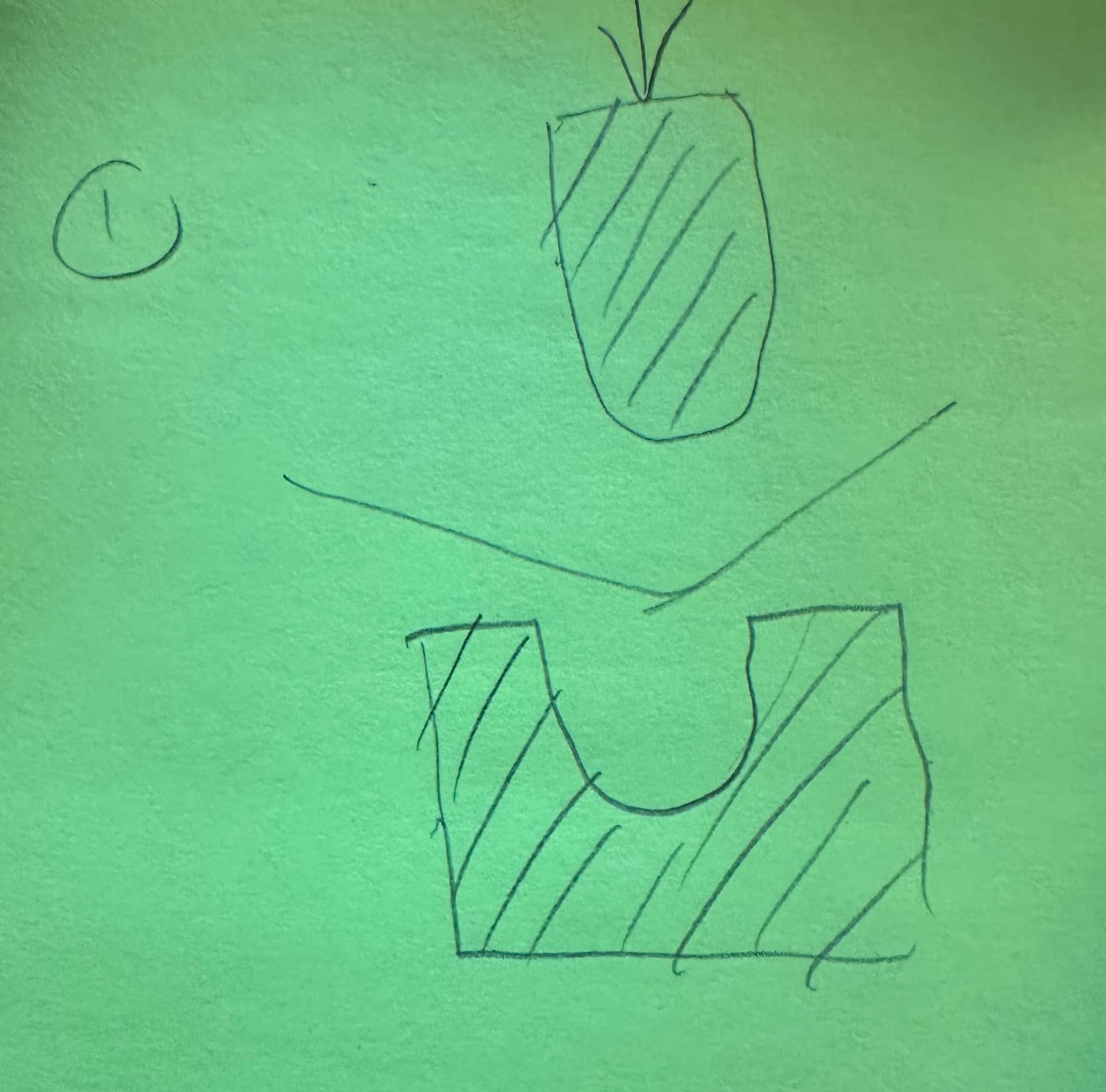
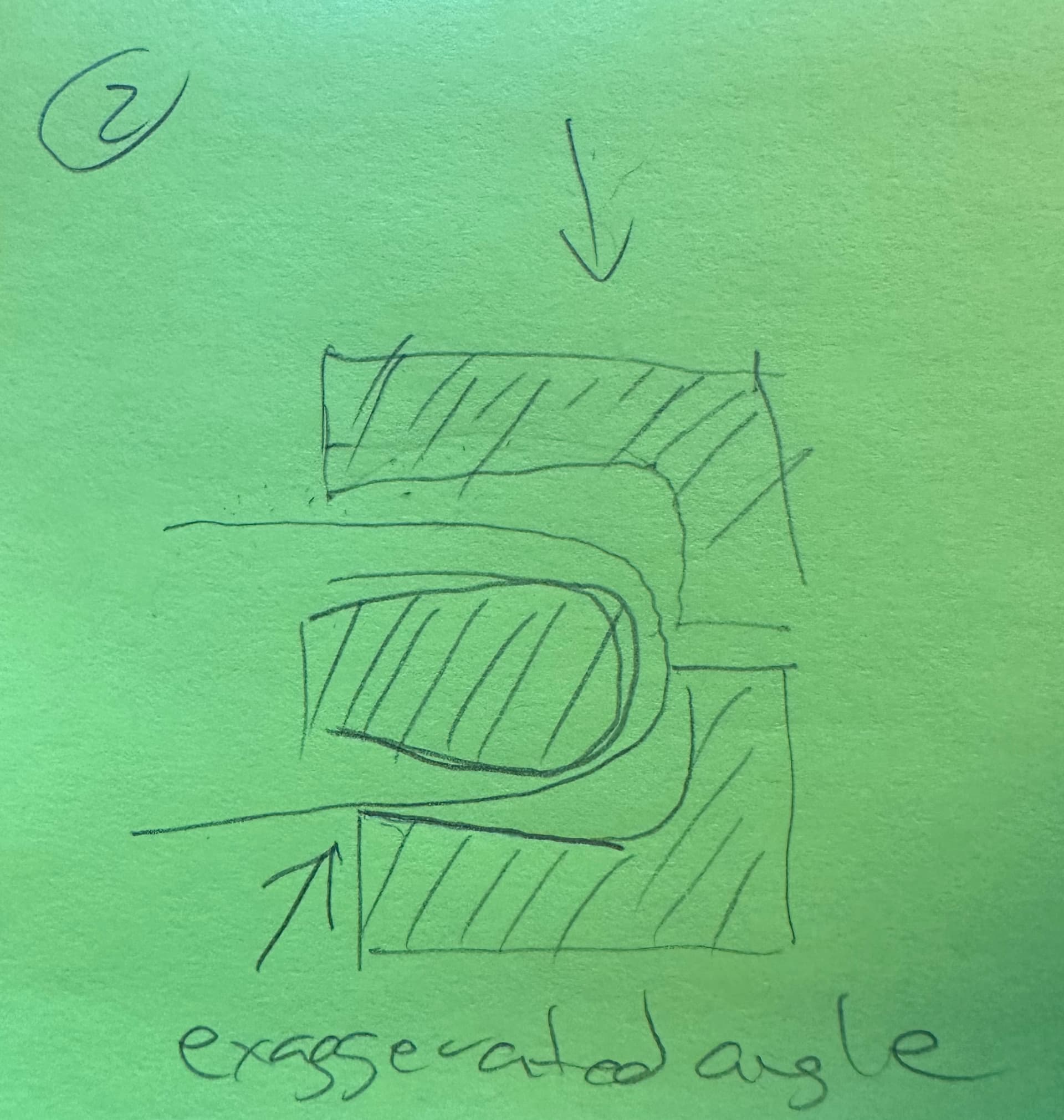
Joe’s right that the steel will spring back away from the bend, so you need to exaggerate the angle a bit. I’m not sure how you’d do that with a U-shaped die, pressing into the U. You could do it in two bends, one to rough the angle pressing down into the U, and a second to bend to the final angle (3 part die?).
I’d recommend thinking about adding some features to your dies to locate the part and the dies relative to each other.
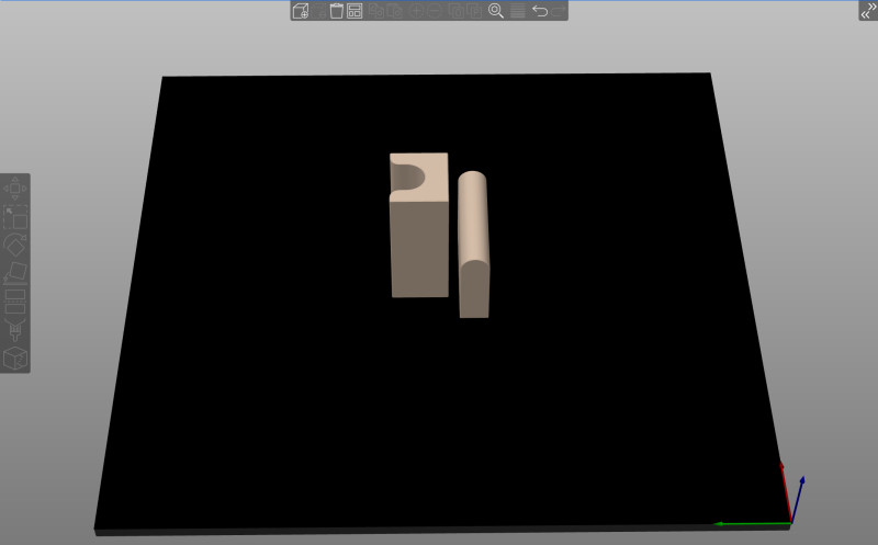
My U-shaped die is 0.75" from outside to centerline, so I’m going to draw some parallel lines on the sheet metal and line them up with the ends of the printed part. I expect the n-shaped half is going to go naturally into the center because that’s where it’s going to deflect the most.
You might just bend the rest of the way by hand to get the desired angle.
Yeah, it should be pretty easy to get from 160 degrees to 180. I printed the two halves with 12 edge loops and I’m just waiting for the plates to get here.
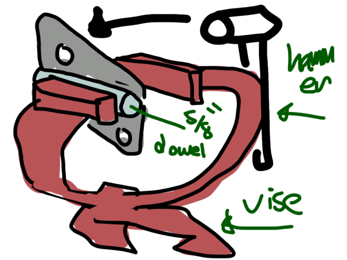
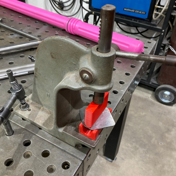
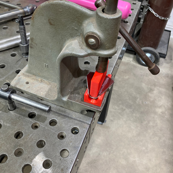
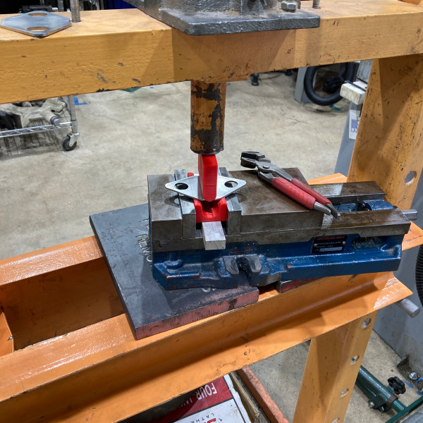
I tried it out with the mini arbor press. As the plate started bending down more and more, the normal force on the U-shaped (printed) part began exerting torque on the center section. I could see the center started flexing up away from the floor and a white stress line appeared on the bottom of the U, so I stopped. I got about 100 degrees of bend. This would work great for thinner metal. It might work with a stronger plastic, or a thicker part. I’d like to try my original plan, holding the bottom printed part in a vise and keeping the inside forces in compression instead of bending.
@mgmoore Can I use the 20T hydraulic press in the metal shop? I watched a video “How to use a Hydraulic Press” which covers the basic operation, safety, and how to avoid damage. I can also show up for in-person instruction. How would I schedule this?
You probably watched the same video I did to learn about it; I doubt I can teach you more. I’ve seen you work and know you are cautious. Go ahead, but I wouldn’t use the compressed air, just the lever. Keep an eye out for any forces trying to push your pieces to the side. (If it can wait 2-4 weeks, we will likely have a new press.)
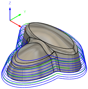
That lower die doesn’t look too hard to machine. I think you could make it out of steel on the Tormach with a ball nose mill.
The radius on the upper die seems like it would be trickier. Because of the length of the die, I don’t know how to do it in a single setup. Using a stop to keep the piece aligned after you flipped it over is probably accurate enough, though.
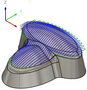
You can do them both in a single setup, and the radius of the endmill doesn’t have to match the radius on the piece. There should be some tutorials for whichever CAM software you use.
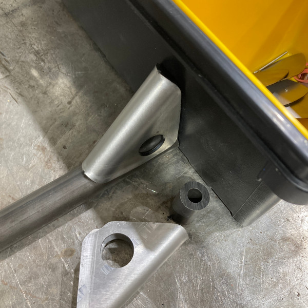
The 3d printed parts worked. It would take trial and error to get the curvature perfect, because where a steel die would form the right shape at the very end, this die will just compress slightly instead.
Oh, yeah, I was thinking about side milling the curve on the top piece, but of course you could do it curve side up. I think you’d still want a ball nose mill of some kind to get a smooth finish on the curve without an excessive number of passes, but maybe the finish doesn’t matter that much.