Hey everyone,
Here’s a description of what’s been done since the last update, what the next steps are to get the fiber laser running, what the known limitations are with the current setup, and finally how we plan to improve the laser in the future.
But first, thanks to everyone who’s helped with the laser: @EricP for providing a lot of the stock/components, machining the front plate, and welding the enclosure + part tray, @JoeN for laser cutting the doors, @jamesfreeman for welding the laser frame, @Andres79 for welding the enclosure frame, @mgmoore for wiring power to the machine, and @dannym for providing the laser source + chiller.
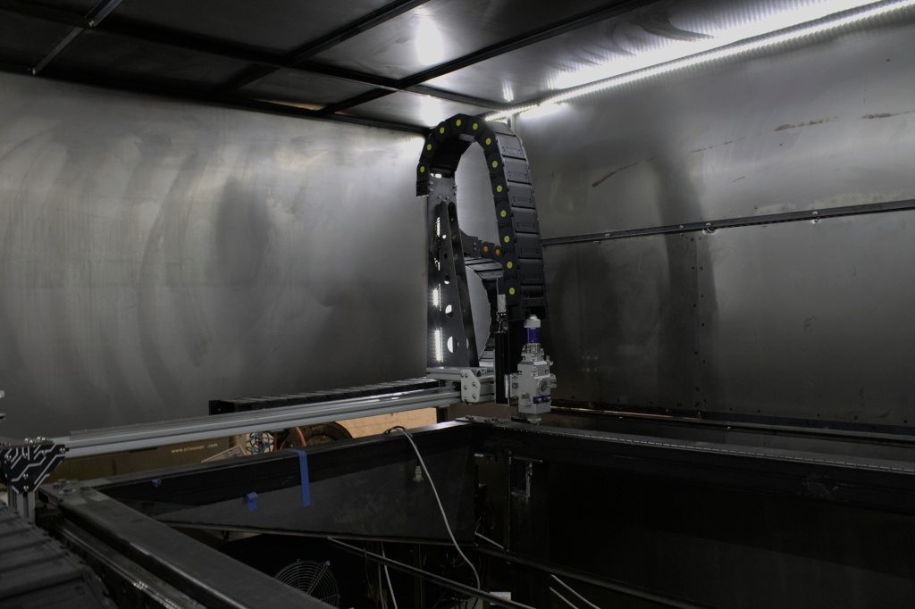
We’ve now got the fiber laser setup in the area where it will be operational, the main axis motors are running, all components are in the shop (other than potentially exhaust tubing), and the enclosure should be good to go.
The next steps to get this machine working are:
Setup air assist
- Off the Atlas’s three stage filter we will add a splitter. One side will go to the high pressure/high flow air assist nozzle, and the other side will go to a regulator to get the 1 bar / 0.5lpm that the laser source wants
- The high pressure side will go to a redundant coalescing filter, then to the solenoid gas regulator
- The gas regulator will then need to be wired to the controller
- The splitter will need to be created. Eric is having someone machine it out of aluminum for the Tormach class
Setup chiller
- Add coolant lines from chiller → laser source
- Attach coolant lines from chiller → laser head
- Right now the power to the chiller has exposed copper leads, we need to install the plug
- Add 2 gallons of deionized water
- We haven’t yet turned the chiller on, but I anticipate that it will need some more refrigerant
Setup exhaust
- We already have a blower on hand, but it hasn’t yet been powered on
- We haven’t yet had a final decision on where the exhaust will be vented out, so we’re not certain how much exhaust tubing will be needed
- Installing all that exhaust will likely be a big task
Setup slat support
- Setup right angle milling head with slitting saw or chop saw with vertical stop and locating pin (similar to dovetail cutting on table saw) and then cut openings for the slats into angle iron
- Weld those support to the frame
- Eric will probably be the one who does this, thanks Eric!
Pass cables through drag chain
- We need to snake the laser, coolant, and motor cables through the drag chain all in one go.
- We will probably have to remove a lot of the enclosure to make that work, and we’re going to need at least 2-3 people
Wire laser to controller
- The coherent laser needs to have it’s control/error signals wired to the ruida controller
- I will probably do this
Set up computer
- The computer needs to have RDWorks installed(@Jon is taking a look at Wi-Fi issue so we can get it downloaded)
- Ethernet needs to be run to the controller
- Will also need some software installed to run the camera(s)
Model / 3D print a connector between the laser head and a webcam
- One goal with the project is to be able to turn on the machine, load your material, line up your cuts, and start cutting all from one area and with the enclosure sealed as much as possible. To do that, it would be ideal to have a webcam both on the head of the laser, and in the corner of the machine.
- I have some really excellent fisheye machine vision cameras that I’m happy to contribute, but we will need a structure to rigidly hold the camera on the laser head with some shielding (perhaps thin acrylic?)
- I’d like for someone to model a connector between the two, and then make it via whatever method they prefer
Paint exterior
- For the time being, I’ve applied a thin layer of rust prevention to the enclosure. We’ll definitely want to add a proper paint finish to both the outside and inside of the enclosure before too long.
- I’m thinking that we paint the outside a glossy white for now, and then after the machine is running we flip all the sheets around so that the white is on the inside. Then we could use the cnc to buff polish the exterior and add a clear finish to make it look really nice.
- When we make the flip we could also laser cut the doors so that they’re all machined straight, ensuring the enclosure is a tight fit
If you see anything here that you think you can help with, please say so in a reply!
After the machine is running, and we have people trained on the machine, then we’re going to begin making iterative improvements, triaging what to change first based on our measurements of the repeatability and what members ask for.
Although we probably won’t begin implementing these improvements for a while, I’d like to list the changes we have in mind, in order of highest to lowest priority as I see it.
Z axis guide
The z axis that I bought has a bit of play in it, so the laser head can move slightly especially during high acceleration moves. Eric had previously tightened it, but it’s not perfect. I think the best course of action would be to just replace the guide with either something higher quality or something bespoke.
Gantry rails
The laser heads seems to bend forward/back by about 15 thou in one area of the machine, relative to the extrusion. I think this is either because the rails are cheap, and/or because the connection between extrusion-> rail is not sufficiently rigid. I think I’d like to add a laser cut steel plate to strengthen the extrusion/rail binding and buy nicer rails for the gantry. Then we can cut down the straight section of the existing rail for the z axis.
In the interim, during the class we’ll point out the area of the workspace with the bow so that you can keep your low-tolerance cuts elsewhere.
Belts
Right now we have steel cored HTD belts with machined pulleys. This will be good enough to bootstrap the machine, however the optimal solution is definitely something more rigid: generally a ball screw or a rack/pinion. Unfortunately, these are much more expensive than the belts.
I’ve given this a great deal of thought, and here’s what I think is the ideal solution. Once the machine is running, we laser cut a rack/pinion from 11 gauge steel. We’d then laminate 3-16 layers, with a slight phase between each layer to make the tooth engagement more consistent. This would give us a very rigid drive at whatever length we want for quite cheap.
If we want to be extra with it then we can grind it against itself, carburize it, powder coat an engineered low-friction surface, and coat with grease.
BLDC
At the moment, we use steppers for the drive because they were cheap and we had two as scrap. Steppers work fine but they aren’t very energy efficient and have a fairly low step resolution. Microstepping increases that resolution, but the torque/step drops down significantly.
I’d like to replace the steppers with brushless dc motors, possibly the same motors that they use on e-skateboards. We would add an analog encoder in addition to the hall encoder on a driver that’s co-located with each motor. With properly gearing the analog encoder will give us a resolution easily in micrometer territory.
Analog encoders / bldc drives can get pricey, but fortuitously I’ve designed a very high quality bldc motor driver with analog encoder for my day job that I’d be happy to contribute.
Lightburn support
When scoping this project, a major priority was support with lightburn. This streamlines the onboard time for users if they already have experience with the other shop lasers. To maximize the probability of lightburn support out-of-the-box we chose a Ruida controller, however, we’re still not sure if lightburn supports this individual controller out of the box. If support is indeed missing, we may want to swap the existing controller with something else.
Enclosure part tray door
At the moment if parts drop between slats they will fall onto a bed that is not easy accessible from the outside. In the future, we’ll add a top opening door below the existing doors that allow easy access to the part tray. Eventually, I think letting all your parts fall through will be really convenient, then the user only needs enough slats to support the material on it’s corners, but we’ll have to try it and see.
Hopefully that wasn’t too much to read. Big thanks to Asmbly for allowing the build space for this machine!
