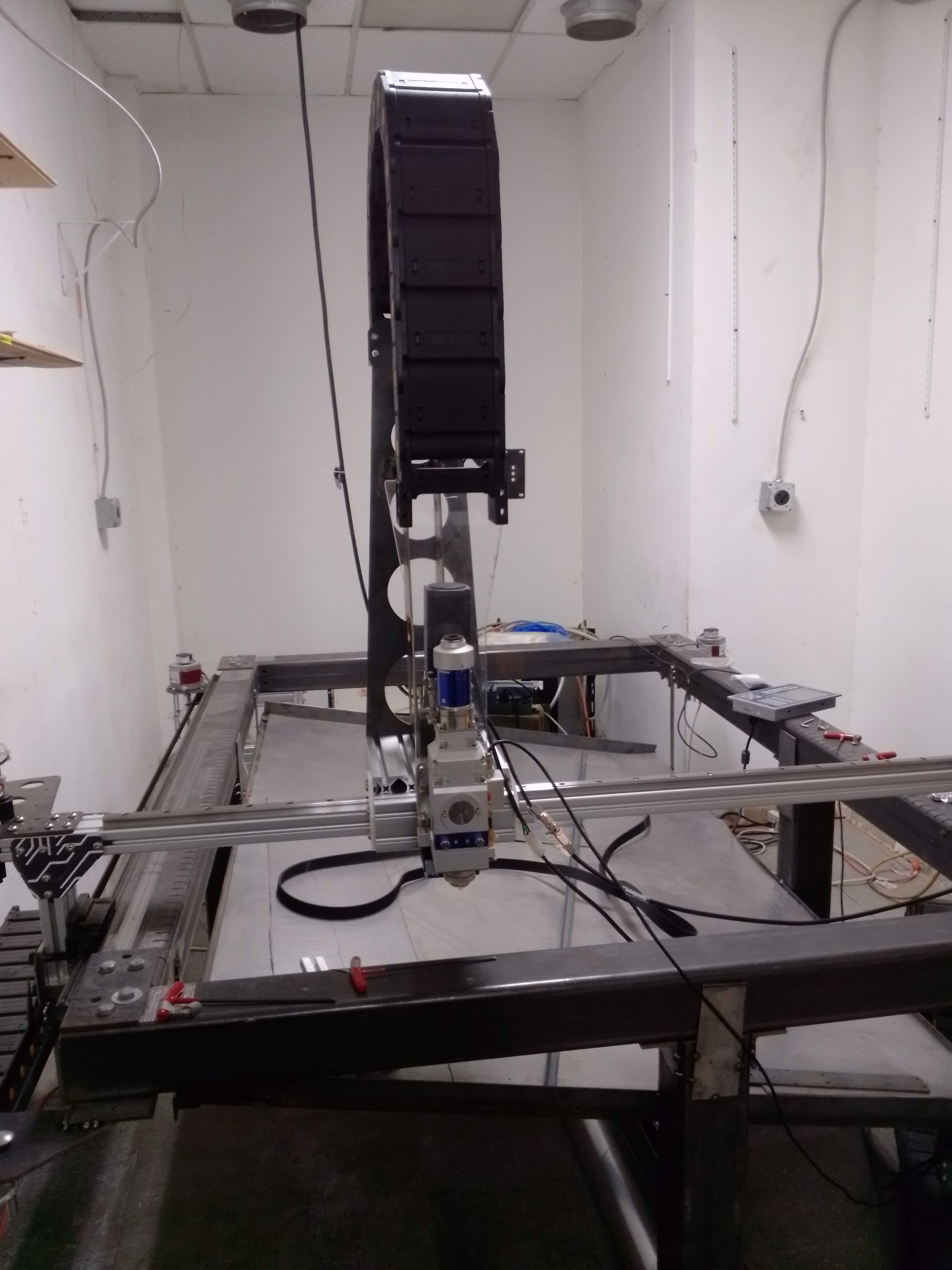
Gantry is almost entirely put together. It should be way over spec in rigidity; currently we have it on three rail cabs. I still need to dial it in to make it properly parallel and tighten the fittings from rail->extrusion, but once that is done and the belt is installed, we should have really excellent repeatability.
The main things that still need to get done are:
We need to pass the laser, motor, air, and coolant cables through the drag chain. I think this is going to be a big challenge definitely requiring multiple people. I’m imagining that we’ll lay the drag chain out flat and use a long stick to pull the cable through
a) If we plan on moving the laser out near the autobay, we need an enclosure. I think the best option would be thin sheet metal surrounding the entire thing. Unless someone can find a cheap laser-safe window manufacturer, for visibility we’ll have to use an internal camera + LED strip. I have some great USB3 fisheye camera(s) that I can lend, but I think Asmbly would need to cover the purchase of stock for the enclosure.
2 b) Otherwise, if we just keep the laser in that room, then the dust prevention / venting is pretty easy. We would probably just draw blackout curtains across the front. I think there’d still be ample space for drying racks on the other side of that room. The laser will also push in a lot of filtered dry air, which could be mutually beneficial.
Right now, the back part of the laser head is acrylic. This is bad because acrylic is brittle and that part gets a lot of vibrational torque. @r1b4z01d dropped off some excellent carbon fiber sheet, someone just needs to mill it out. If anyone wants to help lmk and I can send the file as a dxf
The laser needs to be wired to the controller. If someone else wants to tackle this, that would be awesome. If not, then I can do it.
Thanks to @JoeN for lasering out most of the components, @EricP for adding the tray+adding the power line in, @r1b4z01d for help with the belts+laser stand, and @dannym for the providing the laser source!
Thanks for the update! So exciting to see this coming along
For item #2 – it’s definitely going over in the expanded metal and machine shop area (formerly autobay). I think we’ve got too many other things lined up for the finishing room and it’d be super awkward getting large material over there and inside. I’m not sure the progress on a new layout for metal and machine shops (@Jon has been the point person coordinating that team), but we should make sure we allot ample room for the fiber laser and enclosure.
Thanks for the clear answer. Would it be possible to start moving the laser into the ex-autobay? Sliding the laser around to orient it better once the new layout is ready should be no problem.
I’ll work with eric and call westbrook next week to figure out the budget for the enclosure.
We can’t block the old autobay with the fiber laser; too many people need an aisle for material handling. As soon as the sheet storage moves, the fiber laser can go there.
If you could get me the rough footprint dimensions of the enclosure, it’d help immensely with fine-tuning layout. I’ve got measurements of everything else and I think we’ve reached consensus on how to deal with the loft, so i’ll be sharing some layout proposals soon(ish). Plan to have everything decided so we can do the great rearranging and add power and air drops at the next workday.
@iheartblocks I am back from vacation and I will have time this week to CNC the carbon for the back plate. I will let you know when I get in there. Thanks for all the hard work!
By range, do you mean the vertical clearance? I was thinking of having the rotary attached to the front of the bed, but you’re right that the clearance wouldn’t allow very large tube/pipe. We can switch out the extrusion on the sides of the gantry to raise it as needed.
Is there a particular size of square/round pipe that you want to be able to cut?
The other option discussed is to just have a fixture which drops in to place after removing some of the bed slats. One thing at a time though the priority now is to get it cutting flat sheet reliably.
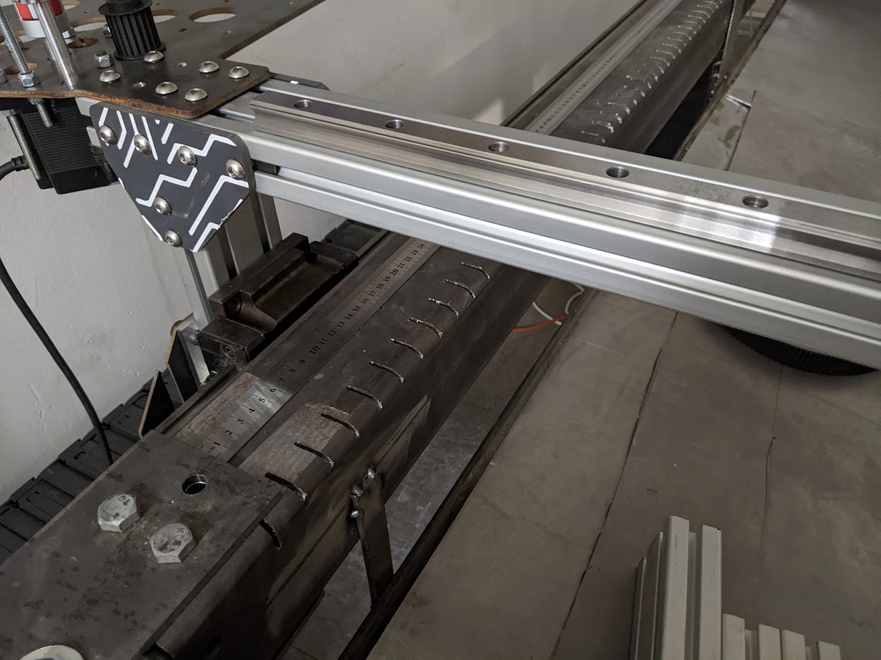
That’s what has me confused- the slots for the bed slats would be vertical. These were cut horizontally. Was this accidentally rotated when it was put together? That’s the best explanation I could see.
The slot bar should not be cut into the structural siderail. That’s a design trap, you can’t change it without replacing the structure, and spacing between slats is not a hard number, it can change with the types of jobs being run. But to fix that, then the sides were cut too close together
These were cut horizontally. Was this accidentally rotated when it was put together? That’s the best explanation I could see.
Are you referring to the fact that the slat openings don’t go down all the way? That was done because cutting the slats was taking too long . We’re going to laser cut the slats anyway, so we can make them fit into that opening properly. I did a test slat on some delrin to make sure it fits well.
The slot bar should not be cut into the structural siderail. That’s a design trap, you can’t change it without replacing the structure, and spacing between slats is not a hard number, it can change with the types of jobs being run
Yeah, it’d be ideal to be able to change the slat spacing, but I think that’s a fairly rare request. If necessary I’m confident we can setup a workaround as needed.
Yeah it’s these slots here. These have to be vertical to hold slats. There’s no stable way to build slats for this unless a new guide is designed. Just hanging them on tabs (like if you were to try to make a “T” shape with tabs) would leave them flopping around, and that’s something that needs to be resolved before cutting the volume of steel needed to make the slats.
The gantry has major stiffness issues. It’s partly because of the way it’s mounted, but the T-slot itself doesn’t have the torsional stiffness for a fiber laser of this span. It’s got to be built on a stiffer member than this.
The Z clearance height needs to be approx 150mm to work with rotary and square stock.
What’s with the belt drive? This is some kind of temp thing? Belt drive come with elasticity and backlash that make it far too inaccurate over this span and with the gantry mass run this high.
Just hanging them on tabs (like if you were to try to make a “T” shape with tabs) would leave them flopping around, and that’s something that needs to be resolved before cutting the volume of steel needed to make the slats.
Yeah, the slats might flop around, not sure how much of an issue that will be. If needed, we will use a circular saw to deepen them.
The gantry has major stiffness issues. It’s partly because of the way it’s mounted, but the T-slot itself doesn’t have the torsional stiffness for a fiber laser of this span. It’s got to be built on a stiffer member than this.
I think I’d respectfully disagree that the gantry t slot isn’t stiff enough for this application. Is there a specific way you’d suggest improving it?
The Z clearance height needs to be approx 150mm to work with rotary and square stock.
That can be easily fixed by using longer extrusion on the sides. If you want to mill that I’d be happy to send you the relevant design file.
What’s with the belt drive? This is some kind of temp thing? Belt drive come with elasticity and backlash that make it far too inaccurate over this span and with the gantry mass run this high.
It’s using a steel core HTD belt. At this length it was much cheaper than the other options, and as I was/am footing the majority of this cost we did what I can afford. If you want to add a gear rack or (preferably) a ball screw that’d be awesome, it’s just not something I can afford.
Yeah, the slats might flop around, not sure how much of an issue that will be. If needed, we will use a circular saw to deepen them
It needs to be a hanger on the sides, not IN the sides. This is easy to cut with a fiber laser with enough Z-height to do it. The issue I see is the oversizes steel sizes aren’t spaced far apart enough so this seems difficult to address
While a fiber laser does not have back force like a CNC, it has to do high accelerations. The 4080 t-slot span deforms way easily as it moves from the sides, so it can’t hold its position or direction.
A belt drive isn’t viable for a lot of reasons. Steel core isn’t a fix, it will actually just bring up more issues. The belt reduction has numerous issues as well- it’s not built with structural belt and axles, but it’s just going off the rails with what looks like a WAY too high reduction ratio.
Ball screws are not just expensive, they’re actually really undesirable for this. The original design was for R&P here
The issue I see is the oversizes steel sizes aren’t spaced far apart enough so this seems difficult to address
Not sure I follow: what is the downside to having the slats in the sides? I could have sworn that was how Joe’s fiber laser worked, but I may be mistaken.
While a fiber laser does not have back force like a CNC, it has to do high accelerations. The 4080 t-slot span deforms way easily as it moves from the sides, so it can’t hold its position or direction.
I’m still of the opinion that the extrusion is stiff enough for a laser cutter. Maybe if it’s an issue in we can replace it with steel tubing in the same orientation. Do you think that would work?
If we do make this change, I’d like to figure out some way to measure the actual impact on cut quality before/after.
The belt reduction has numerous issues as well- it’s not built with structural belt and axles, but it’s just going off the rails with what looks like a WAY too high reduction ratio.
The reduction is currently 9:1, from the math I did that got the precision where I wanted it without being (imo) too slow. It’s designed such that you can move the belt over to easily make it 3:1 instead.
I do agree that the belts used in the reduction are suboptimal. I was imagining replacing it with a proper laser-cut gearbox after everything is running.
Ball screws are not just expensive, they’re actually really undesirable for this. The original design was for R&P here
If you recall, I had told you in September that we were using a belt because I never received the specs on your R&P. Still happy to switch if you (or someone else) wants to contribute one, but as-is I think it’s best to stick to the belt for the time being.
That one has a slot rack attached to the structural member, but the slots can’t be cut into the structural member for a number of reasons, and I don’t think any design does that. The slot rack needs to be a separate component for a number of reasons. You already ran into the first problem- it’s too hard to cut. It has lots of other issues that have no real fix- it’s putting the location of the slats too high, there’s nothing to hold their angle. This needs to be addressed before cutting the slats because it’s a lot of material that will need to be replaced if it’s cut like that.
It’s easily flexing through torsion from light pressure without even being in motion, so this isn’t working from a design perspective. I don’t see any tightening or tweak to fix this, it’s not a problem with a bracket. The structure needs to be based on something with greater stiffness.
Steel is only moderately stiffer than aluminum for the same size. It can still be aluminum, and aluminum is probably still the best choice, just not that size, not in T-slot. The head design needs a much lower offset. The huge sweep up top is contributing to the problem in a big way, the cable should not be run through this.
9:1 will be VERY slow unless the pinion is large. It looks like a 1"-1.5" pitch dia right now but this can’t be fixed by using a larger pinion either. Precision does not come from the step-down ratio at all- and this belt drive is limited to somewhere around 1/8-1/4" cut precision overall, which is not very useful.
Laser-cut gearboxes wouldn’t have practical value. The design’s looking for <10 arcmin of backlash, and durable- there’s just no reason to be doing it that way.