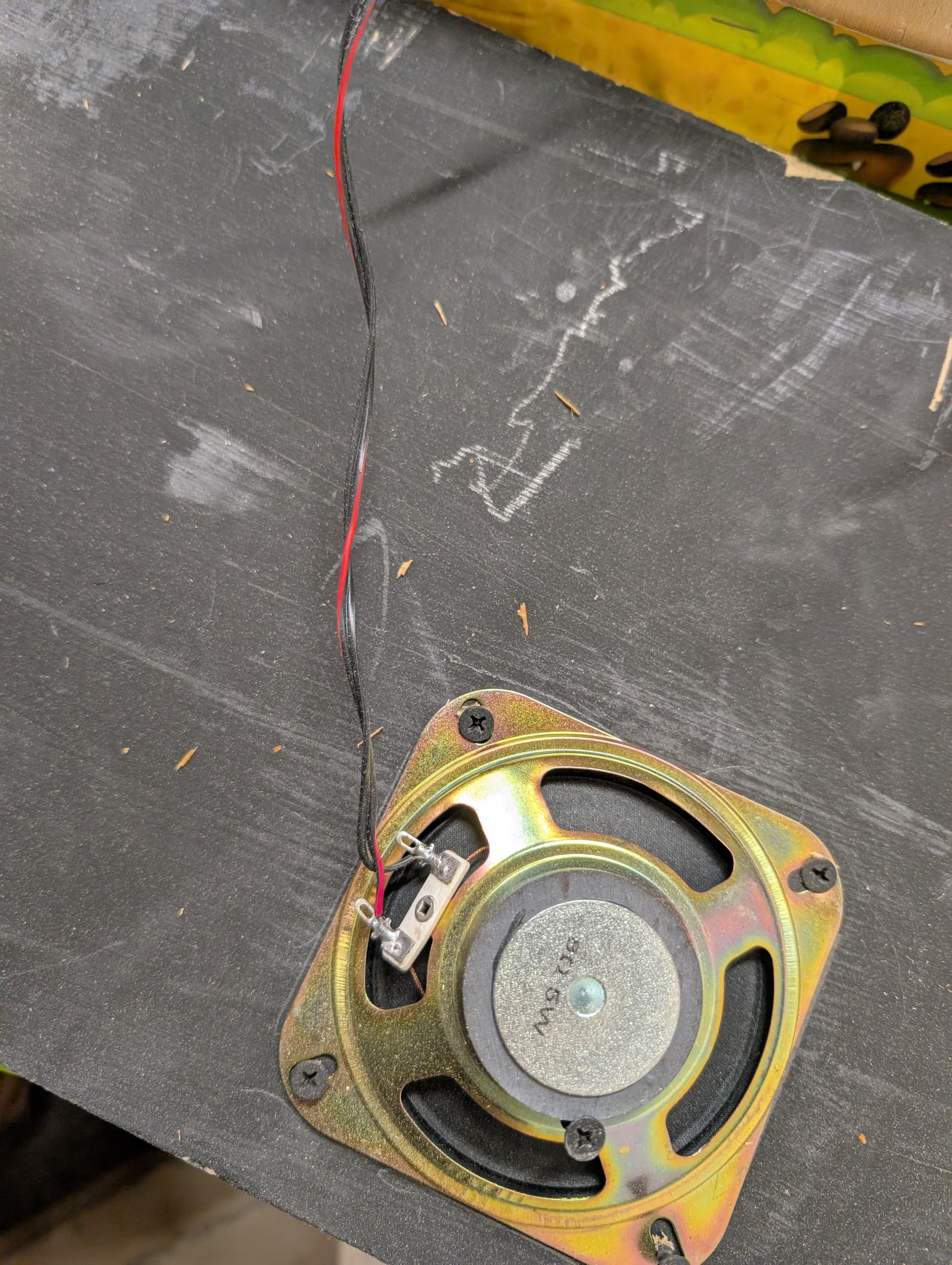
I found this setup for a game called Bolirana. It’s got some sounds that come through while the game is going, but there’s no volume control and this thing plays very loud!
I feel like I could drop a potentiometer in this speaker line so I could turn the volume down in some settings.
This is possible, right? Is there a “Pot for Dummies” kind of explanation to this that could jump start me here?
I think your thinking is sound: a potentiometer is really a variable resistor. So a resistor in line with the speaker would lower the volume.
The catch is: the signal to the speaker is amplified, so a resistor/potentiometer would have to dissipate a considerable amount of power (maybe 5-10 watts?). There are high-power resistors, but you’d be looking for a more specialty part (look up L-pad) than we keep around.
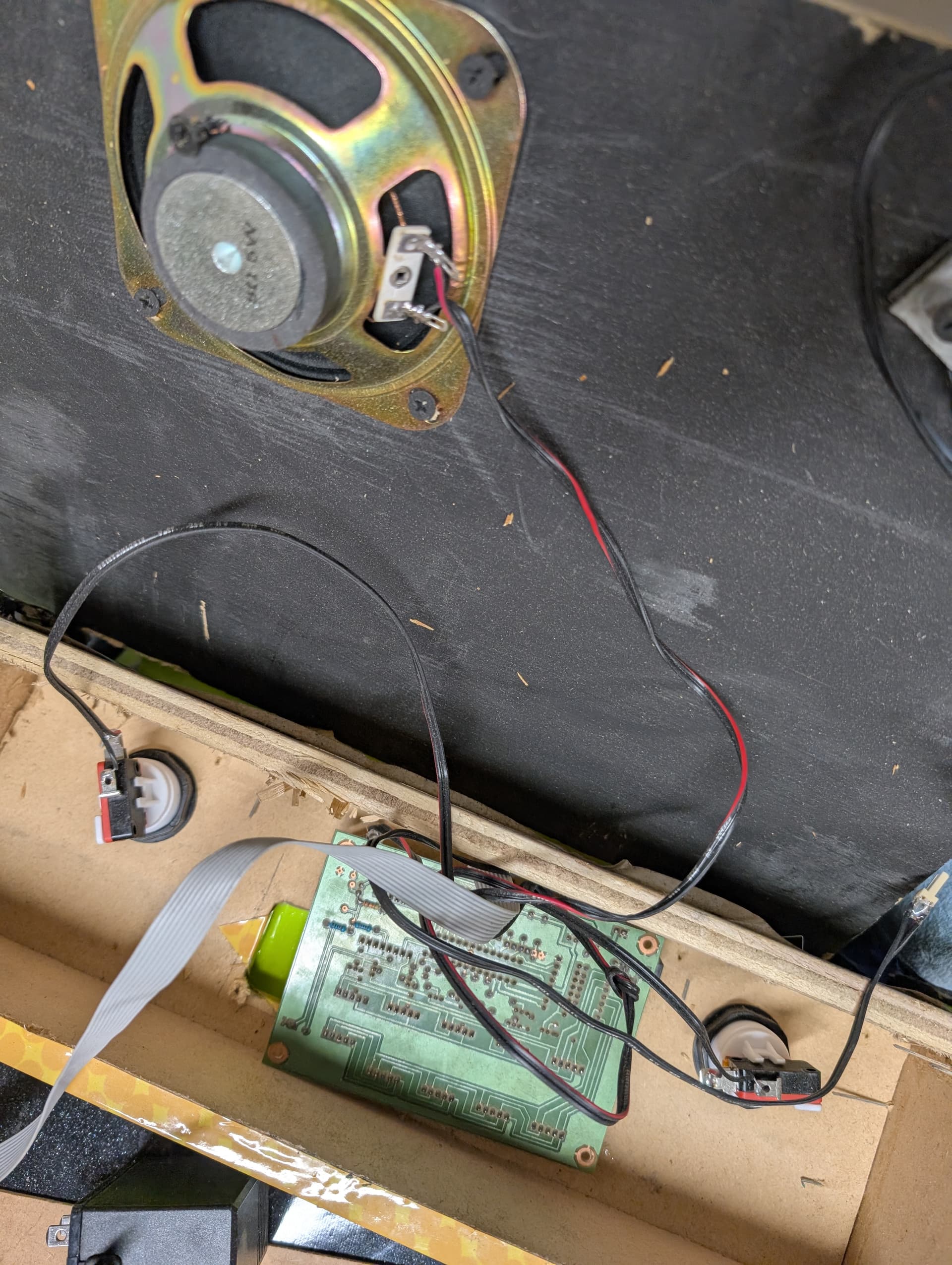
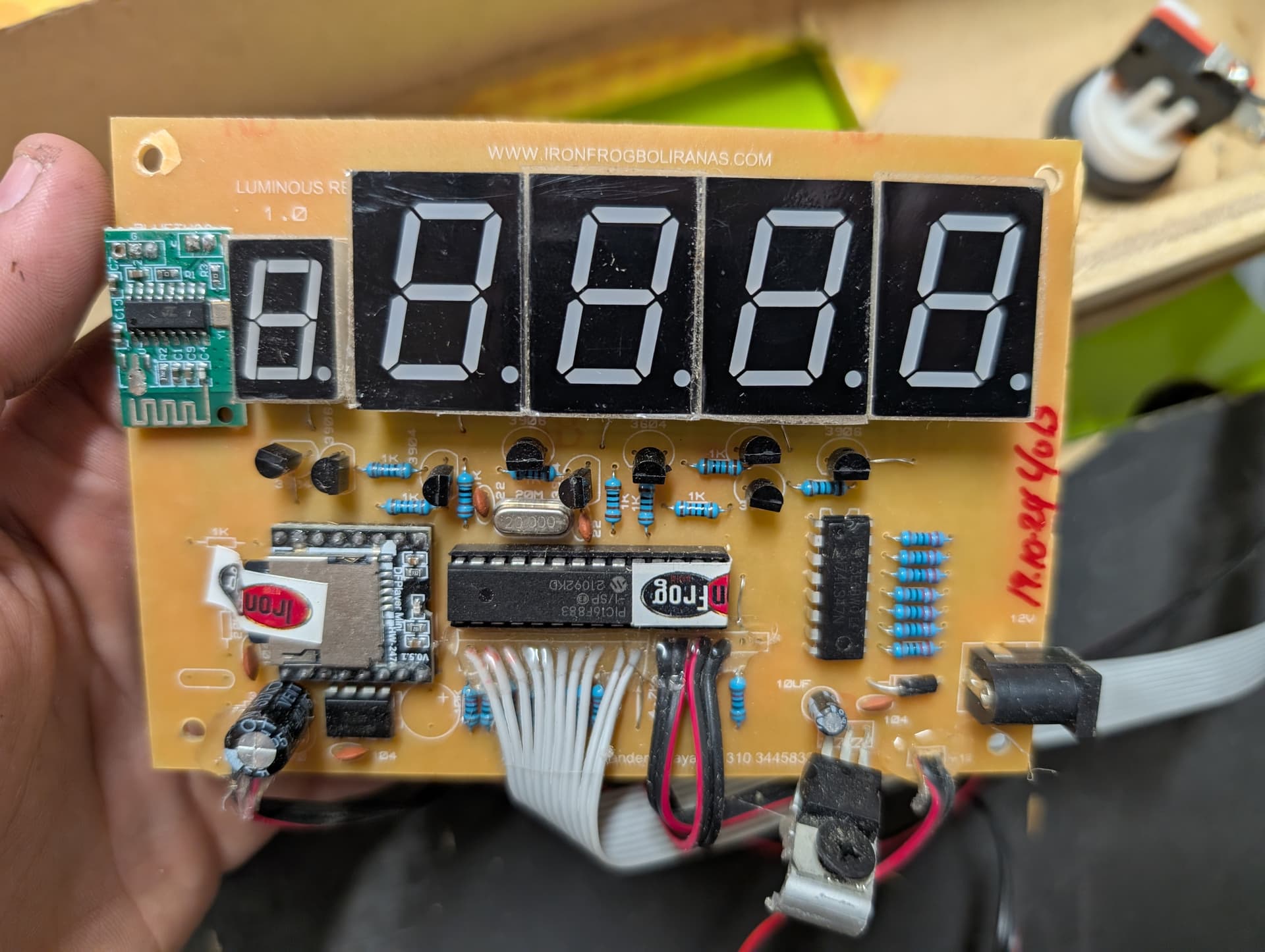
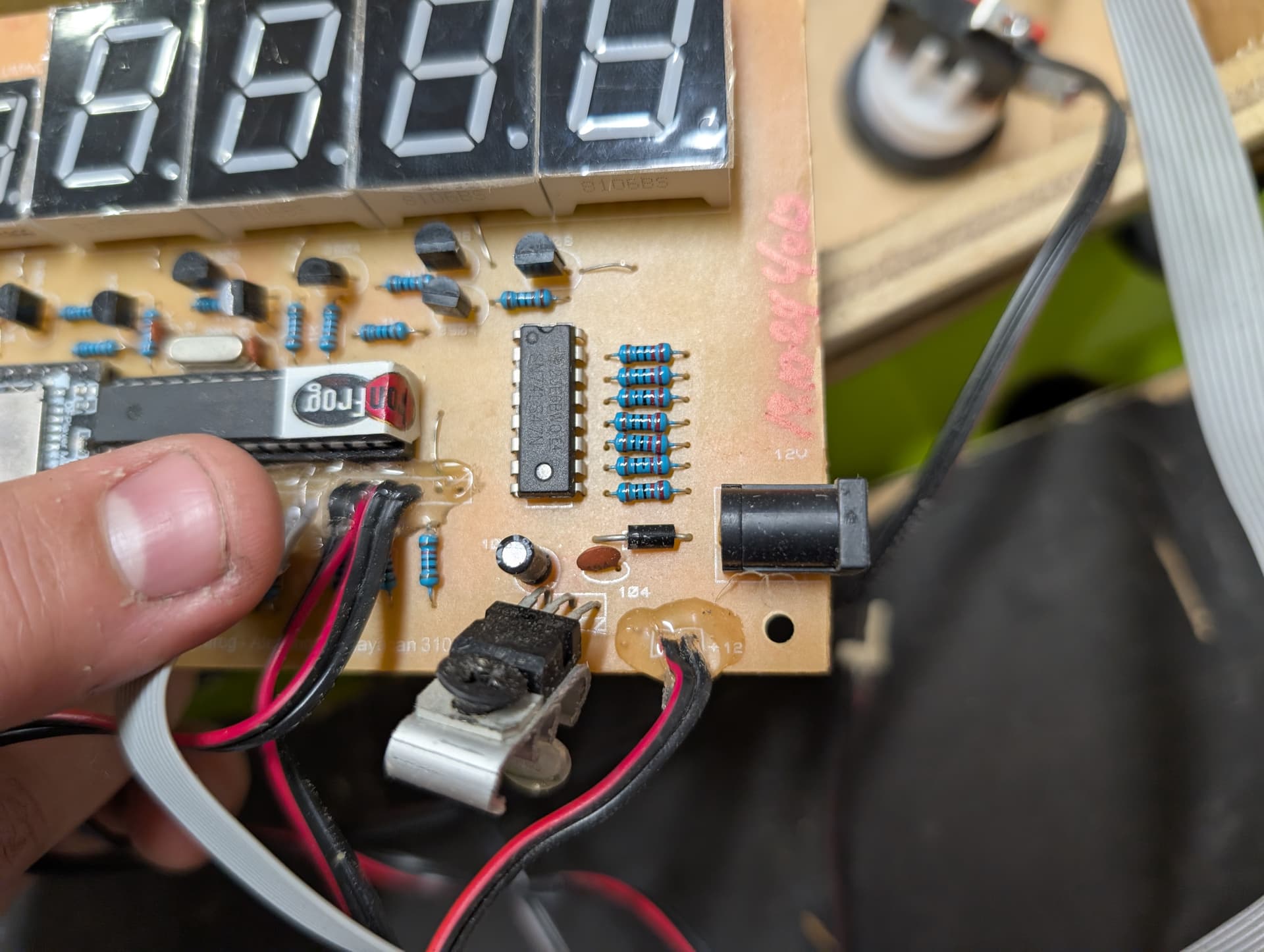
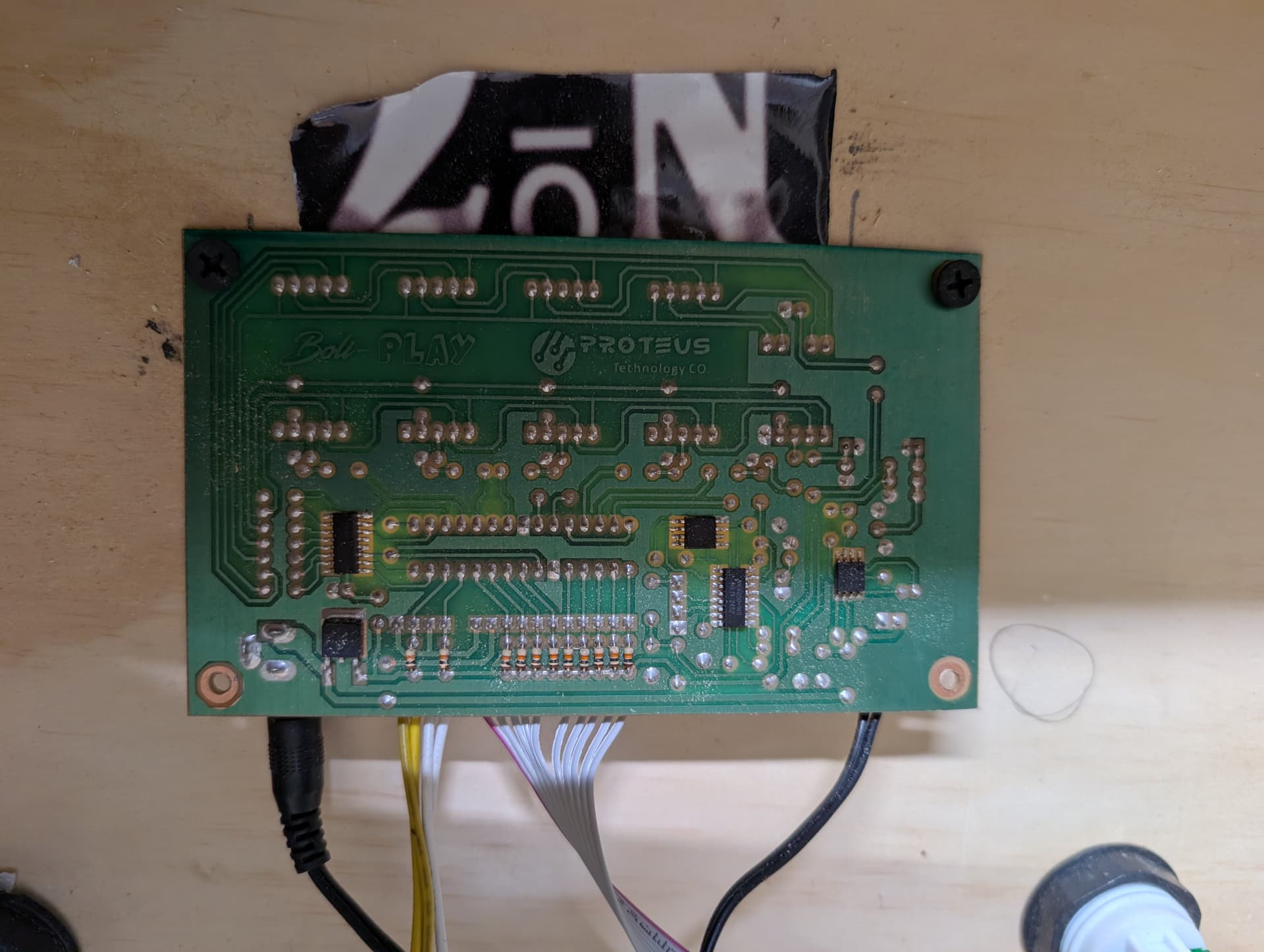
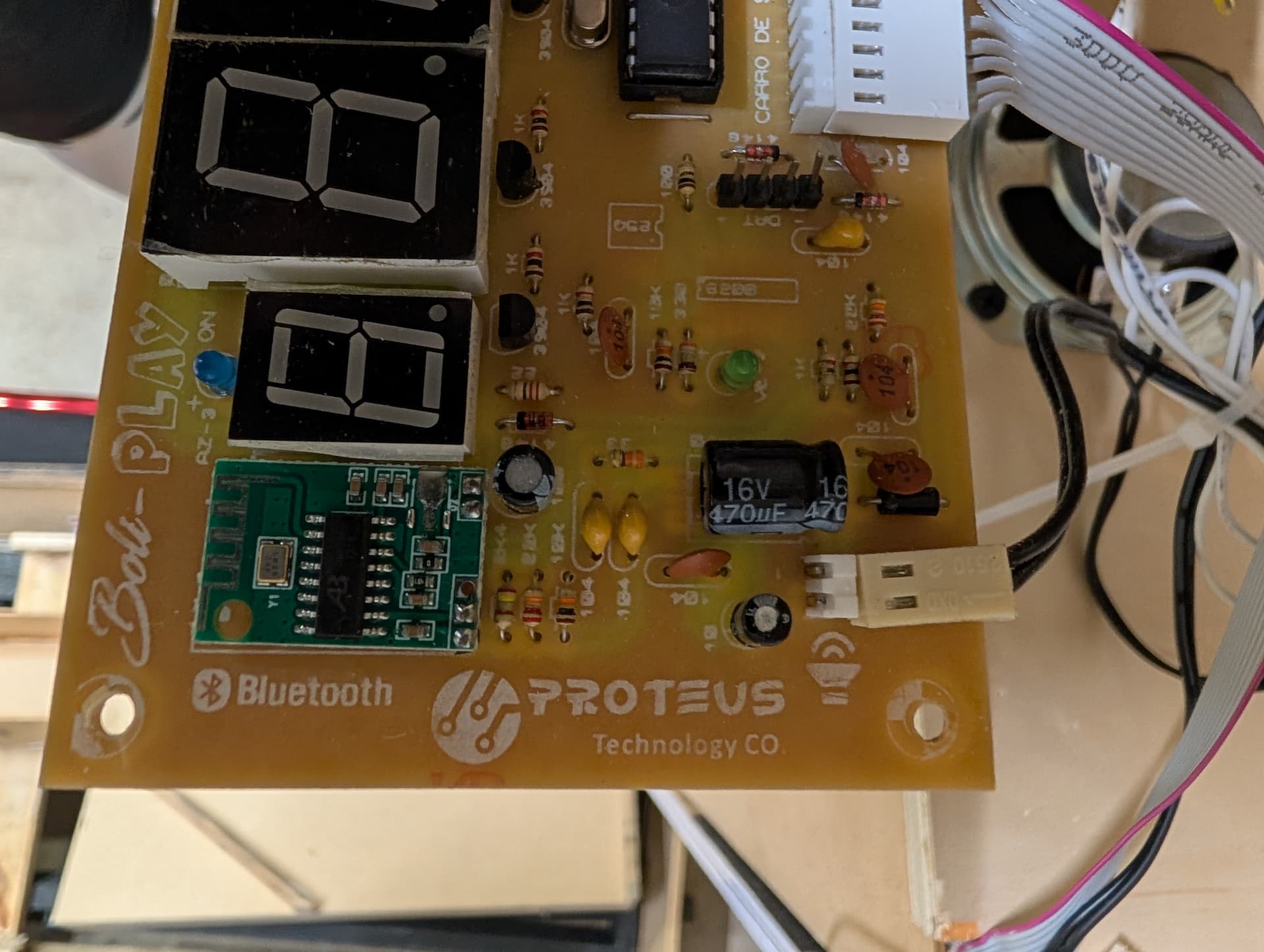
Ideally, you might find something on that amp board to tap into and lower the volume. Could you post a photo of the front of that board?
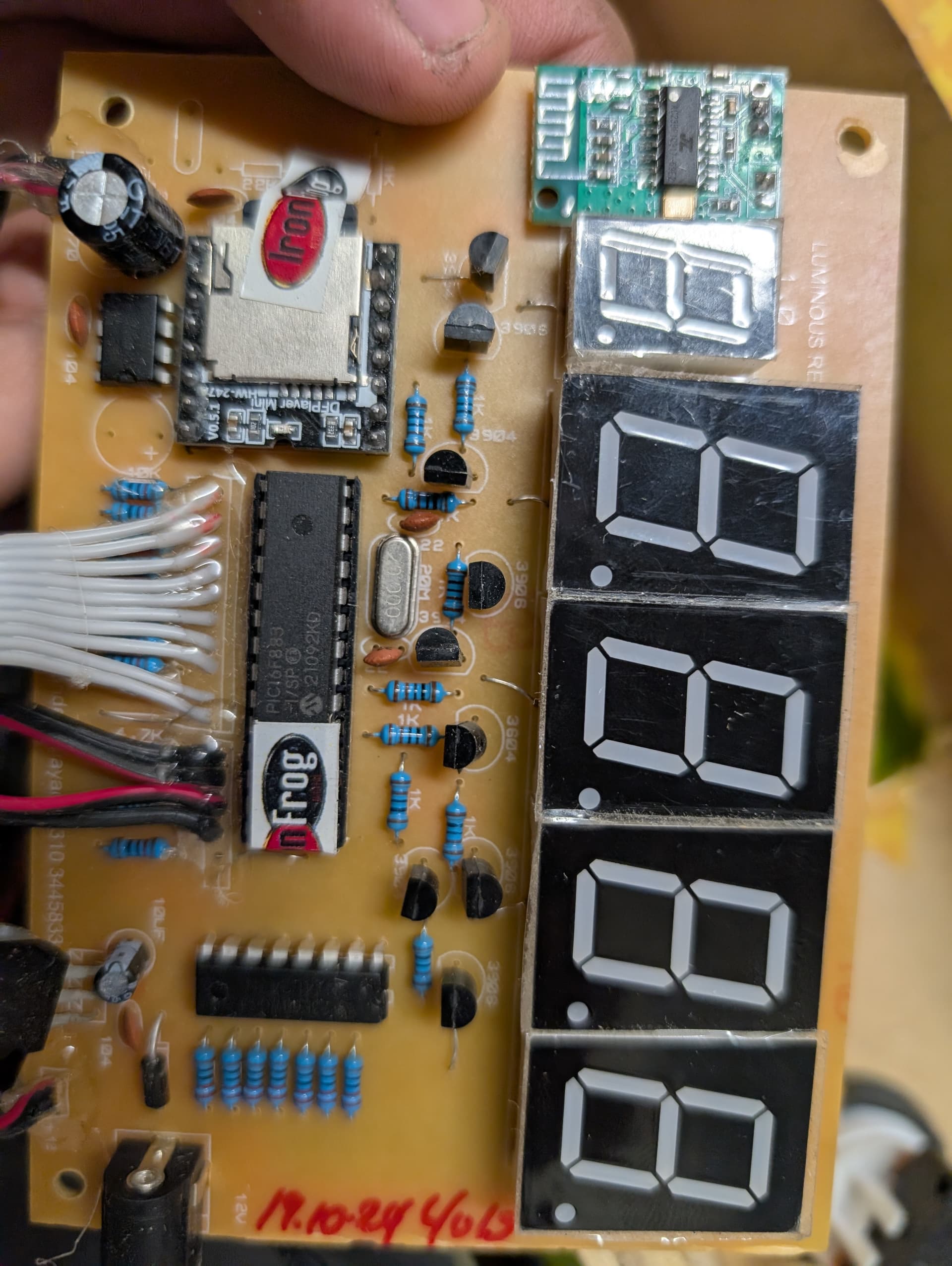
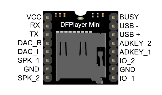
Luckily those are some pretty standard components with available datasheets. I’d assume that the PIC microcontroller in the center is signaling the DFPlayer Mini board to play sounds on cue which are output to the speaker via the SPK1 and SPK2 pins. The DFPlayer Mini can output up to 3W, so a 5w potentiometer might be a simple and cheapish solution. It would be pretty inefficient though, turning some of that 3w into heat when it’s playing sound. This shouldn’t be enough heat to matter other than inefficiency.
I agree that using the potentiometer to lower the signal before it’s amplified for the speakers is best, if it’s possible. It might be tougher to do that if it’s all happening on the DFPlayer Mini and it’s only receiving the instructions to play the sound file.
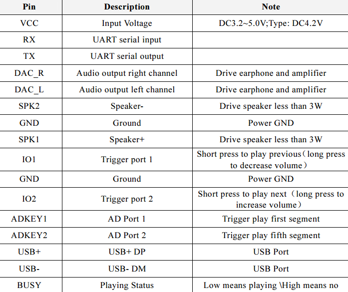
This chart from their wiki says that you could wire a momentary switch to IO1 and IO2 and use long presses to adjust the volume, which might be the best option.
You found a wiki for this?? I have been looking all over for something on this board and haven’t been able to find that.
I found out how to adjust the volume. I’ll attach a video. Y’all might have saved me from needing to mess with any wiring here. Although if I had it my way, I’d like to have something a little bit easier to make adjustments.
I know this is just for a game and the power resistor and potentiometer solutions would likely also solve your issue, but I just wanted to expand John’s mention of L-pads. They are typically slightly more expensive than a similar pot due to being a bit more rare, but are in exchange more versatile for randomly attaching one to a speaker in a cabinet in that they don’t change the impedance of the load as seen by the amplifier output circuit or a filter/crossover network, which could potentially alter the frequency response (depending on what it is connected to). You typically find them as the tweeter attenuators in speaker cabinets.
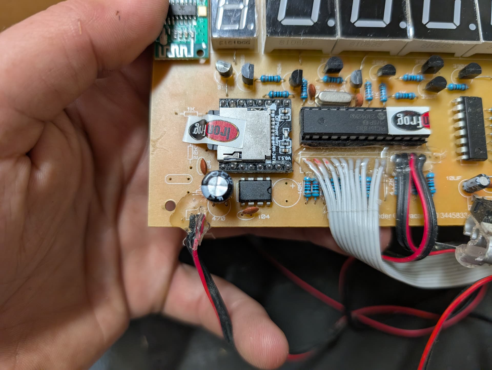
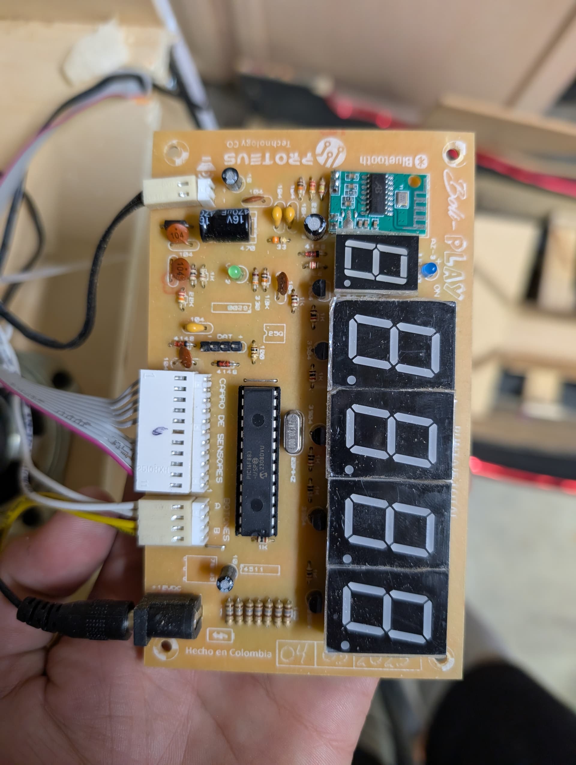
That second board looks like a slightly different setup. Pretty curious about how the Bluetooth module comes into play (not the least because of the three pads on the left corner that make me want to believe it’s for a pot haha).
or its just the stereo audio line input (of which only one channel is soldered? or maybe the ground is connected with the power?) for bluetooth speaker output? or maybe that’s reversed, bluetooth source and audio line out mixed to the speaker? that chip is a “Bluetrum”. I recognize the logo.
Something to keep in mind is that L-Pads like the one referenced above are not designed to attenuate a single down to silence. They are designed to provide a measure of control to balance drivers (“speakers”) in a multi-driver speaker enclosure. If it were me, I would use an inexpensive audio amp on a PCB, which would give you complete volume control. You would need to add a resistor ladder to bring the speaker signal down to line-level, which is what the amp requires for input. You would also need to supply power to the amp, which could be done with a USB power supply. Here’s an amp that sells for $12 on Amazon: Amazon.com