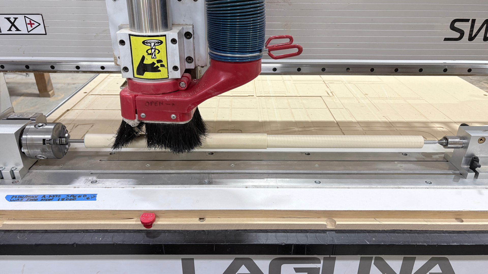
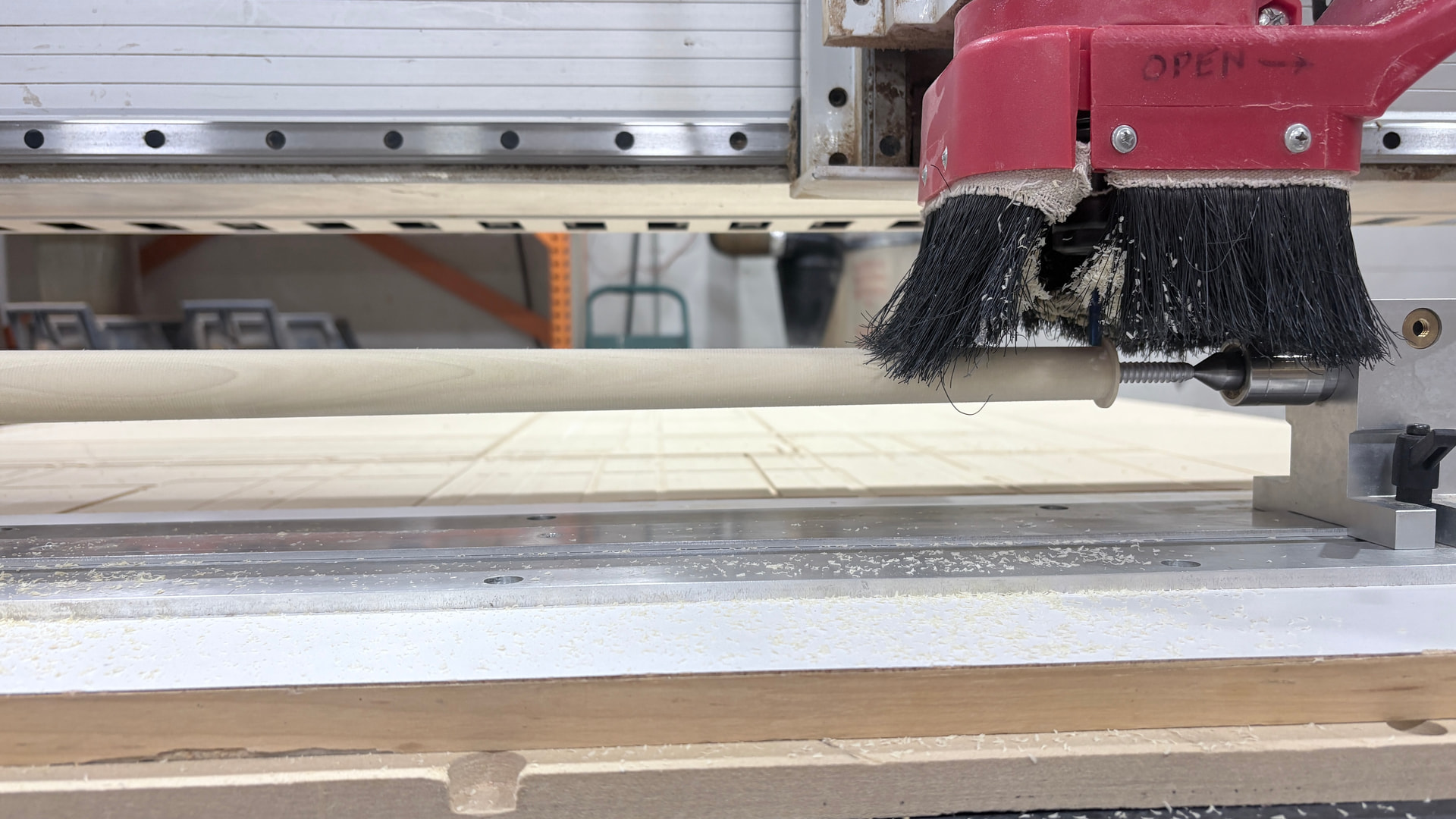
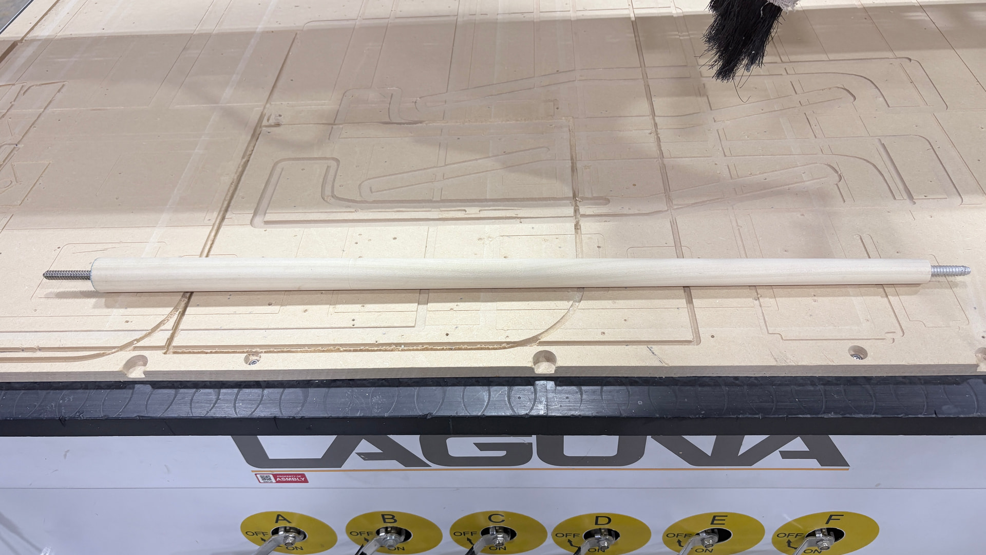
With many thanks to @bwatt and @atwatsoniii, I was able to cut a conical taper on a 29" test piece that turned out almost perfect. 29" is the length of the pool cue butts I’m making. I’m using Vcarve and a 1/4" end-mill bit. I say almost perfect cuz the dimensions in Vcarve are for a taper from 1.25 to .85 (diameter). The actual dimensions are 1.277 to .8455, so a little big on the large end and a little small on the small end of the taper. All in all - very pleased! The whole process - rough and finishing passes took 2 hours.
I’m running a test on a real cue blank this weekend. Multiple fingers and a few toes crossed…
There are two alternate cutting strategies for this scenario, and they would probably be much faster and yield better results.
One, since the taper angle is small, you would simply tilt the jig at that angle. Then an endmill can just go from end to the other at constant Z. Since Z does not change, there’s no Z-stepping marks to remove in a finishing pass. You would only need a modest overlap of the toolpath per rotation so it can go fast.
The other would be to put the bit on the side of the stock and cut with the side of the bit, not the tip. Flank cutting avoids putting all the cutting in the flute tips and has some more subtle benefits.
Since this ultimately becomes somewhat thin and not entirely rigid, really flank cutting wins here. When tip cutting on top, the force of cutting is perpendicular to the turning axis, trying to bend it, so the work can tend to flex and chatter, especially if trying to speed up the job.
The bulk of flank cutting’s force, on the other hand, is down the taper’s central axis which will not flex. An upcut bit will, however, make some degree of upforce with some tendency to chatter. It’s probably not much but a straight flute bit would not have that at all.
Flank cutting does mean the toothpath does scallop which gets significant with higher linear feed per workpiece turn. It is possible to combine the two- tilt the rotary axis to the taper angle, aggressively rough off the side with flank cutting, then go top cutting to finish and remove scallops. The linear feed per work rotation can still be high and get a smooth finish because there’s no Z-stepping, and with very little material to remove in this pass the perpendicular cutting force is negligible even at high feeds
Thanks for your thoughtful response. Good suggestions - a flank cut while offsetting the tailstock might also be a way to go. The most important aspect that I’m looking for is repeatability and accuracy of the diameter at the small end of the taper(critical). At this point, I’m ok with 2 hour run time.
You mentioned chatter and that’s a major concern. I’ve bored out the entire cue(wood dowel center) and replaced it with a reinforced carbon fiber tube. That reduces the flex of the cue significantly and hopefully will take care of any chatter. We will soon see…
Yea, accuracy will be tough in this setup. The tailstock has a bit of slop on the rail we could try to take out in the future.
You could also plan to take two finish passes. After the first finish pass, take your measurements, and you can compensate in the last finish pass by adjusting the model dimensions. I admit that’s tricky, but it would in theory compensate for any kind of inaccuracy.
The second thought is, if you can give your stock extra length on both ends. Then create a jig to cut it down to size and put the inserts in.
Yes, there’s news. On several test pieces, I found that the hole holding the pin at the small end of the taper isn’t centered after the cut…(I should problaby change the title of this thread to “Conical Taper Fail”) My best guesses are that the pins weren’t sitting perfectly straight in the blank, or the jig wasn’t in perfect alignment with the X axis — probably one or the other. Either way, I’m holding off on running the red cue through the CNC until I sort it out.
On the plus side, I borrowed an idea for centering the rotary on the X axis from Dorian: taping a laser pointer to the carriage and aligning it with the same edge of the metal rotary base at both ends. Tested it today and it worked great.