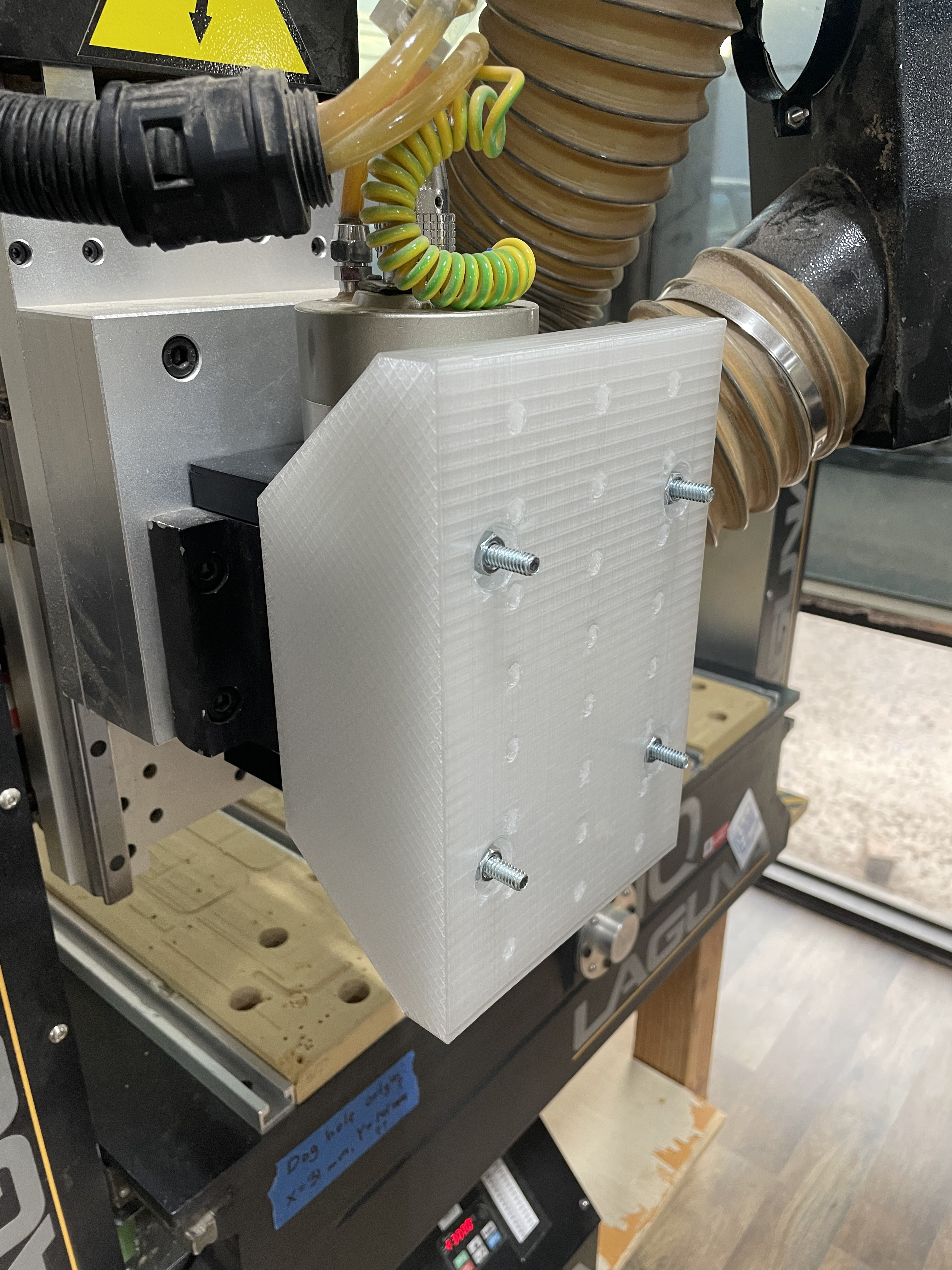
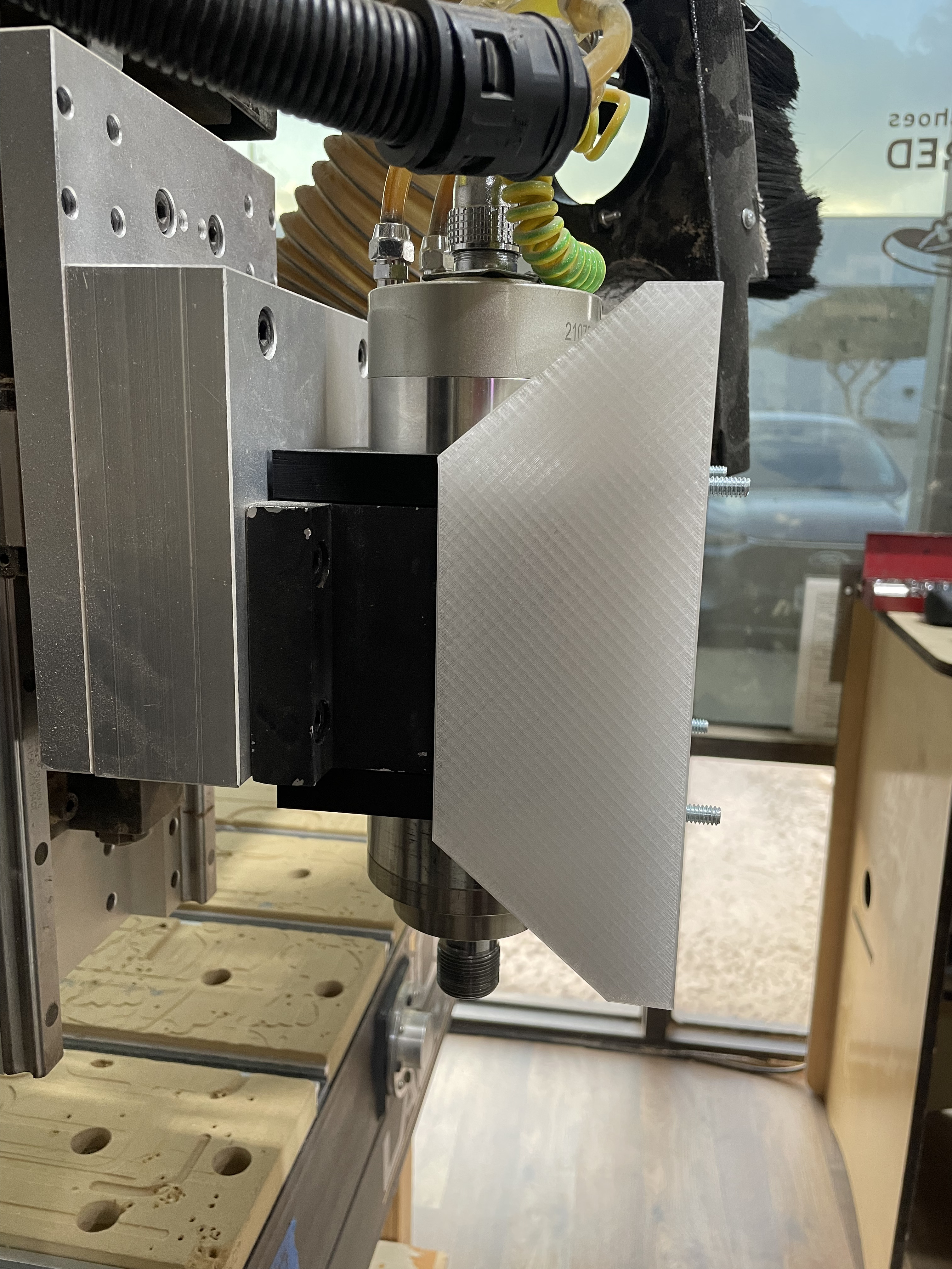
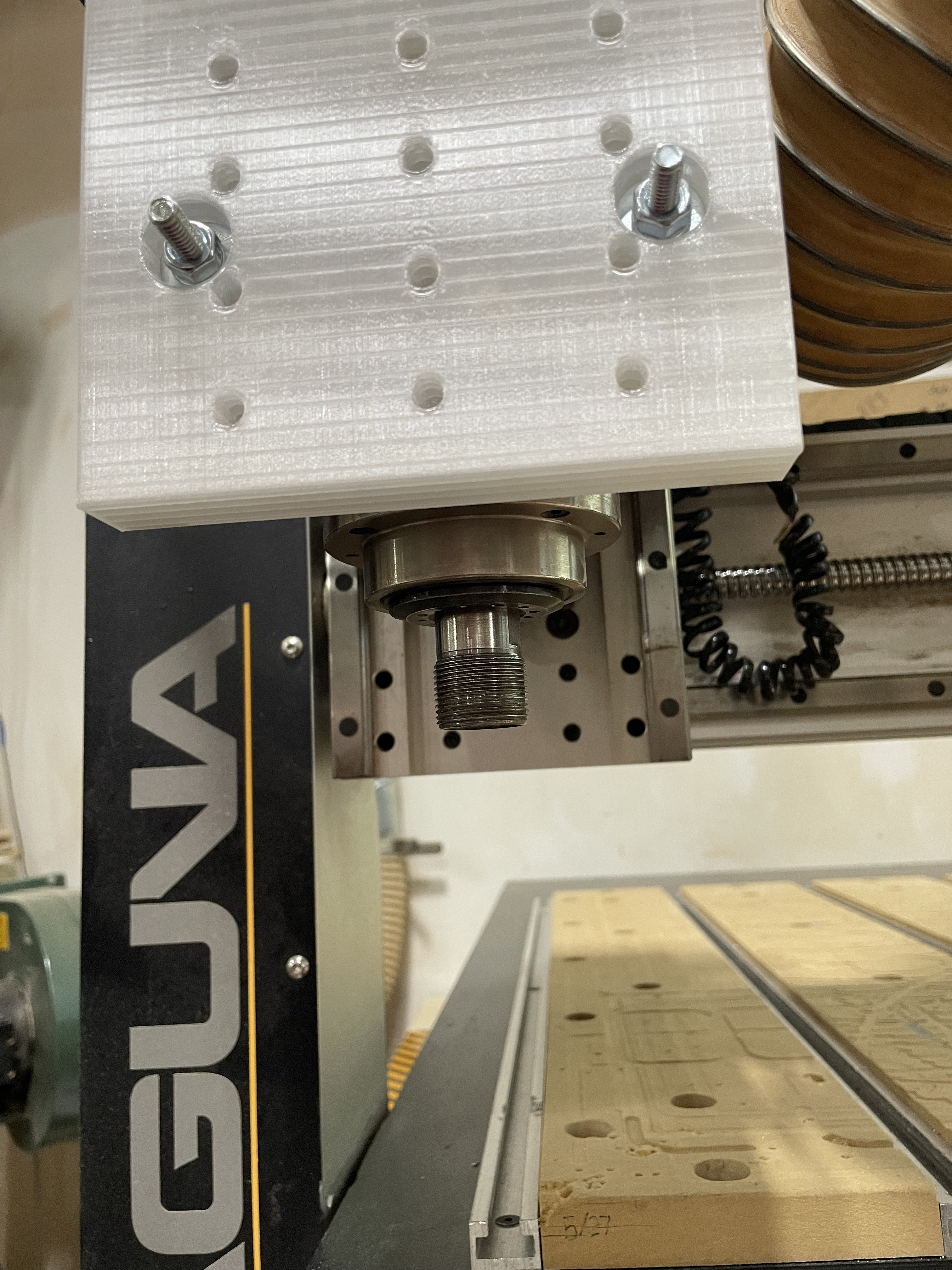
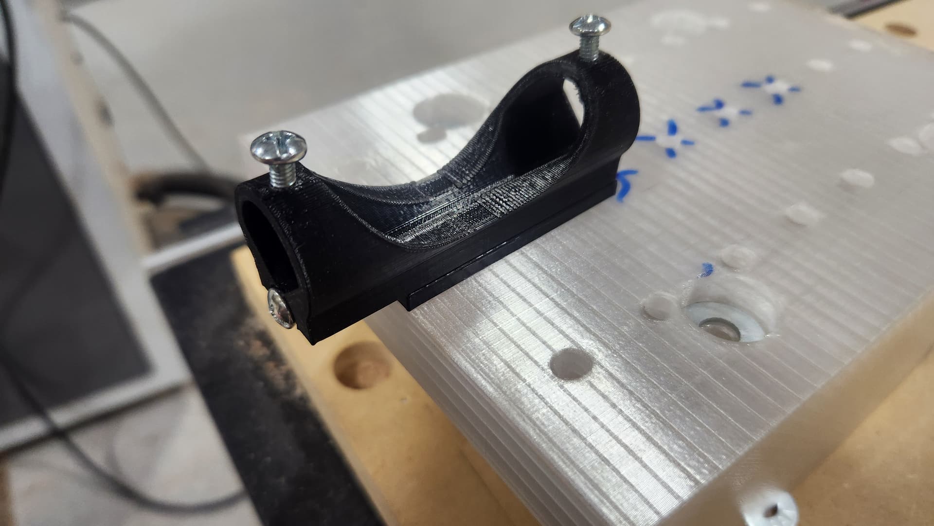
For some work I’m doing with the large and small CNCs I have created a mount plate for attaching various other “secondary” tools - for example, a pen, a brush, etc. The mount is 3D printed in PETG and snugly fits directly on the front of either of the CNC’s spindle mounts. Its array of holes are for 1/4”-20” or 6 mm bolts (actual hole diameter is 6.5 mm). The column of holes are 40 mm apart, and the rows are 25 mm apart. Note: The bolts shown in the picture has been shortened and are now flush with the surface of the mount plate.
The front mount easily allows access to the spindle collet shaft, but it does require the bulky dust boot to be removed when it is attached to the CNCs.
Thanks Brian. It would also be useful to attach an accessory like a laser, like we talked about at the CNC SIG meeting. I have investigated that option a little bit and decided it is probably too much effort to support properly and most likely not a change Asmbly would want made to the machine. I don’t think manually turning on/off the laser would be accurate enough. I reached out to a company that builds add on lasers for CNC’s and they do support the Laguna but the changes required are invasive. Here is there reply:
Thank you for your inquiry about using our laser with your Laguna IQ CNC, which uses the RichAuto A11 DSP controller. We have thousands of customers running this same set up with RichAuto controllers. Since the RichAuto lacks a native PWM output, the standard approach is to intercept the spindle relay signal (Y1/S0 terminal) using a Single Pole Double Throw (SPDT) switch. This allows toggling between spindle and laser modes without excessive relay wear. The lack of PWM output does mean that the Laguna will only be able to turn the laser on and off which eliminates setting fractional power via toolpaths and software.
Key Wiring Steps (Based on J Tech Photonics Guide):
Locate Components: Find the RichAuto controller in the control box. Identify the Y1(S0) terminal (spindle control output) on the top-right connector.
Intercept Spindle Signal:
Disconnect the existing Y1(S0) wire (going to the spindle relay) and connect it to the “SPINDLE” side of the SPDT switch.
Insert a new wire into the empty Y1(S0) terminal and connect it to the switch’s common (middle) terminal.
Connect the NEGATIVE (black) signal wire from your laser driver’s input to the “LASER” side of the SPDT switch.
Power Connection: Insert the POSITIVE (red) signal wire from the laser driver into the +24V terminal on the RichAuto controller (both wires should fit securely in the screw terminal).
Mounting: Position the laser driver near or inside the control box. Use extension cables for routing through the cable chain to the gantry. Refer to laser mounting specs here: https://jtechphotonics.com/?page_id=602.
Controller Configuration:
Access the pendant menu: From the main screen, press MENU > Machine Setup > Spindle Setup.
Set both Spindle ON and OFF delays to 0.00 (delete existing value and enter 0.00, then OK).
Exit to the main screen.
For visual wiring diagrams (older/newer controller styles) and full details, please review the J Tech Photonics RichAuto upgrade guide: https://jtechphotonics.com/?page_id=7637.
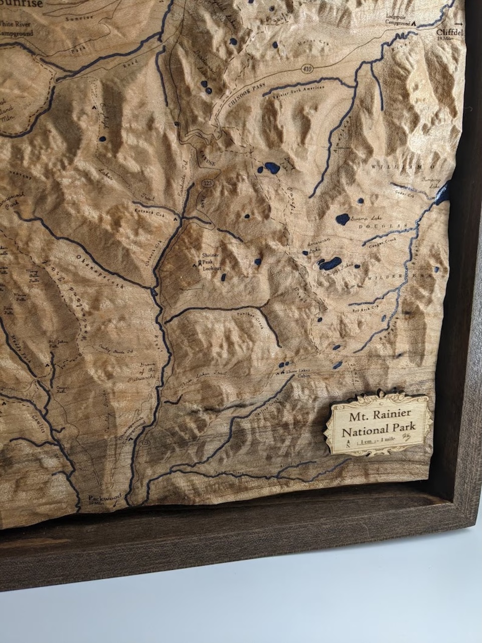
Yes, dynamic control of the Z height which we don’t have with our lasers. Here is an example of a terrain carve from Etsy with intricate laser etching.
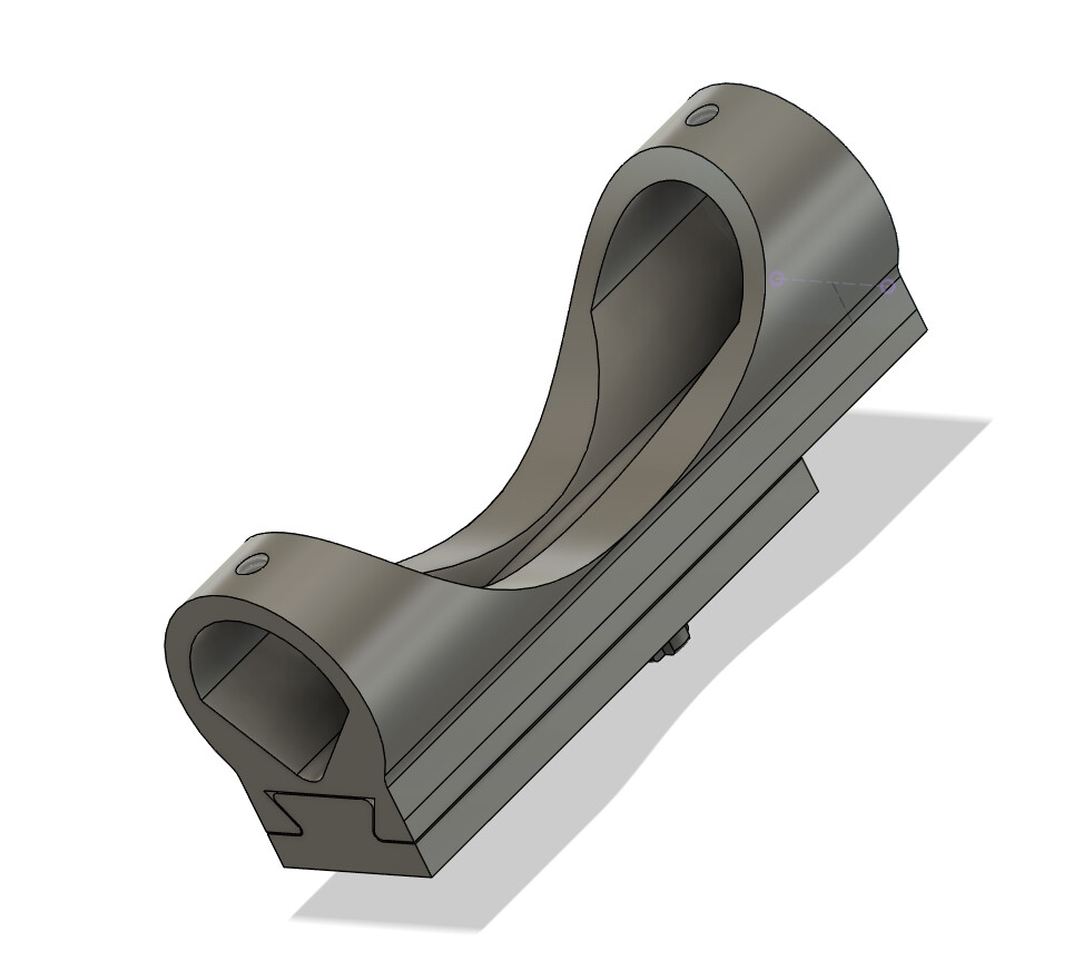
Introducing the first BrianPlate™ compatible attachment. A pen holder. It features the ability to accommodate writing implements up to about 0.8 inches, adjustable spring tension, and tight tolerances (some might argue too tight!).
It will be available for use whenever we end up storing the BrianPlate.
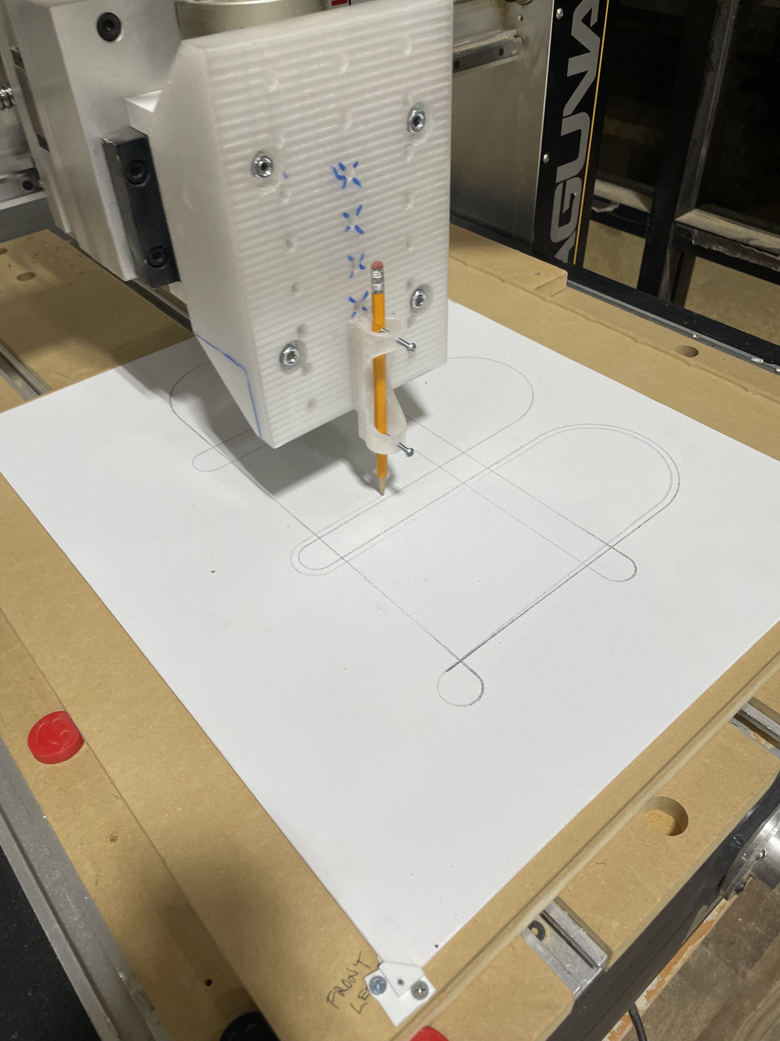
@Kasper, Is your pen holder available (can I borrow it) or better yet can you send me the STL files for me to print one myself. I’m working with @cjromb and want to mount a paint brush to the small CNC. Bri
Of course!
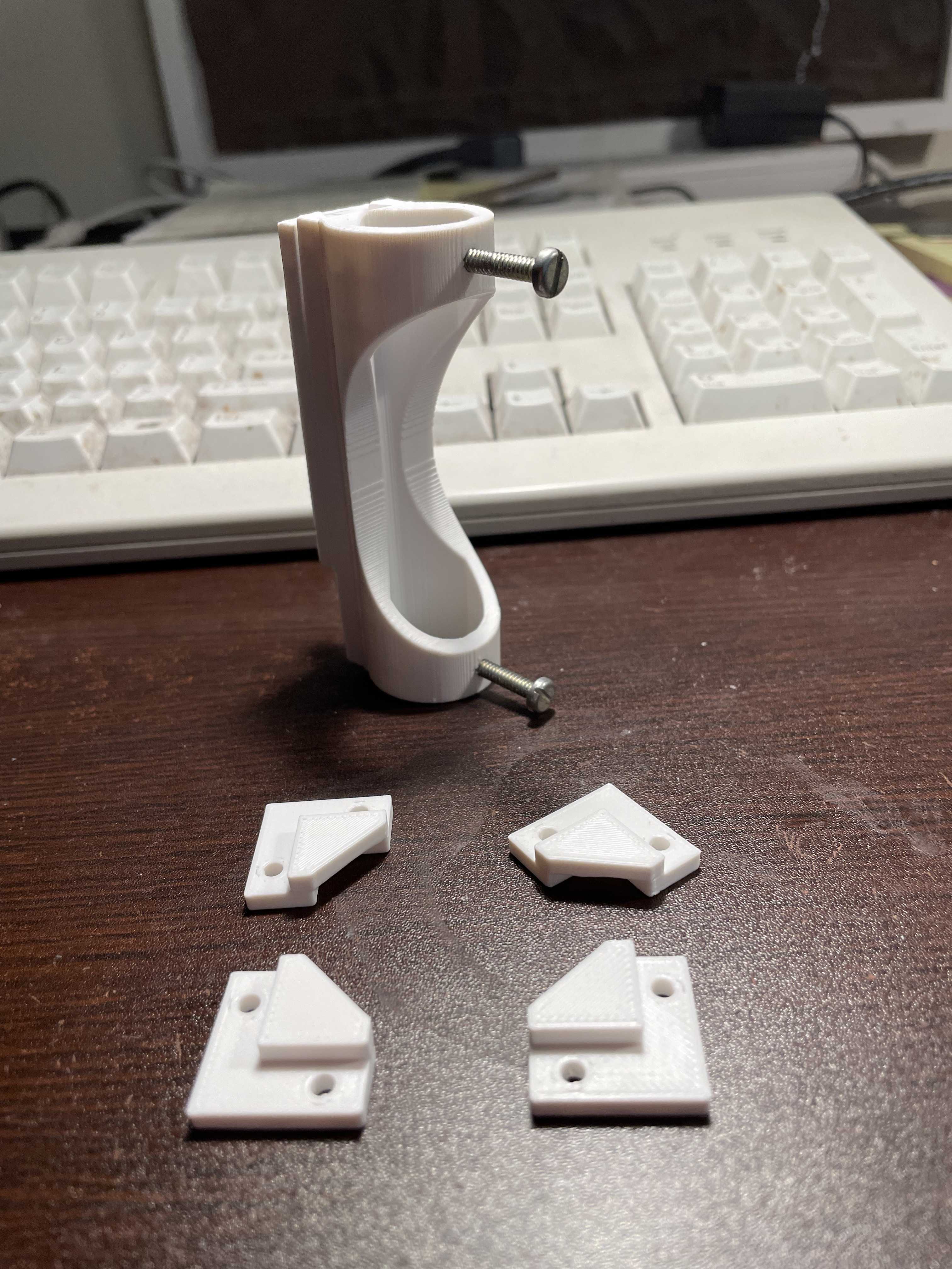
I would print the base at 99% scale so you have a little more clearance in the sliding mechanism. I can also email you the fusion file if you want. PenHolder_Holder.stl (164.1 KB) PenHolder_Base.stl (241.1 KB)
Thanks so so much, they are printing in PETG as I’m typing this (with base at 99% in all dimensions). No need for the Fusion file. What are the screw (dia, TPI & length) and spring (dia & length) sizes?
I had some troubles getting a bolt to fit into your base piece to mount it. It kept rubbing on the holder slot roof. Or the head was too big of diameter or a hex head. Finally I found a flat-head bolt in the shop that worked.
Also I’d add a hole in the holder through to the base’s mounting bolt giving it access to it. This would be instead of having to take it all apart to unmount it.
But otherwise it worked like a champ!
P.S. Send me a STEP file and I’ll modify it in FreeCAD.