I’m trying to get a PCB made that combines two circuits, a wireless charging receiver and a microcontroller board.
Inductive Charging Set - 5V @ 500mA max
Adafruit GEMMA M0 - Miniature wearable electronic platform
One of the challenges is that I’ve only been able to find the datasheet for the chip the receiver is based on in Japanese. But I was able to find a similar circuit on a site that used to sell a set like this, which convinces me I at least have the right reference design.
I’ve built the basic circuit using the receiver board and the Gemma, and it seems to work well, but I want to package these up to be smaller (and drop some components that I don’t need).
I’ve tried mashing up the circuits, but this is the first time I’ve designed a PCB, and I’d appreciate it if someone could look over the resulting circuit and tell me if it looks generally reasonable.
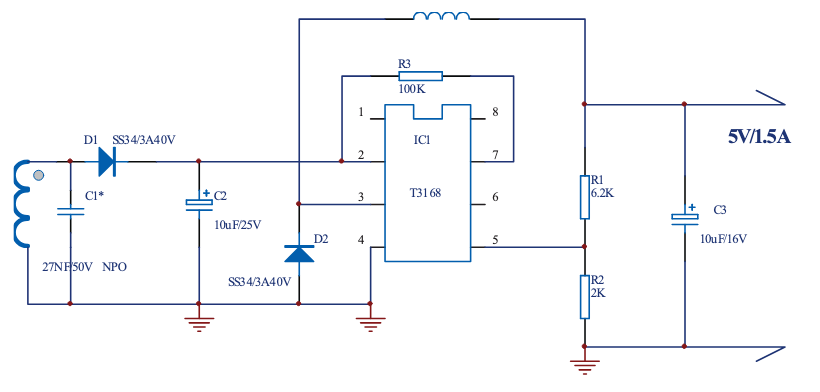
Here’s the receiver circuit reference design:
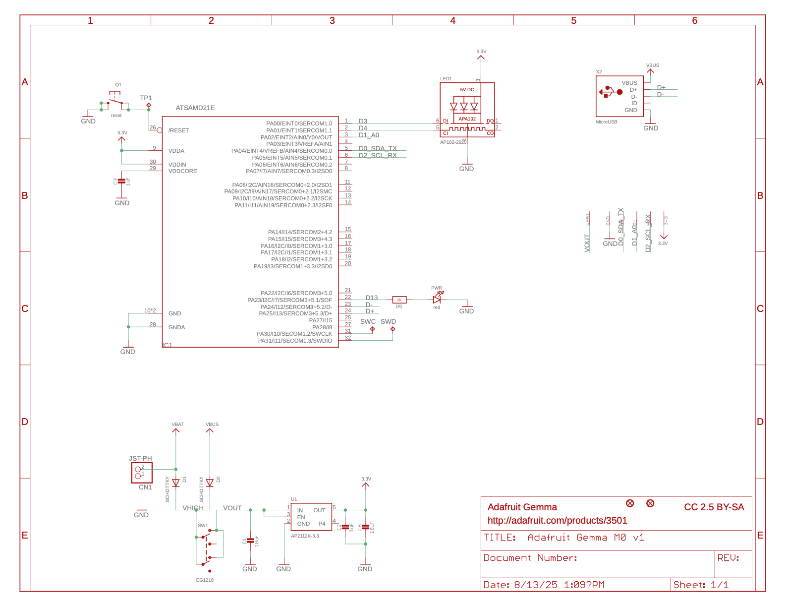
Here’s the Gemma (courtesy of GitHub - adafruit/Adafruit-Gemma-M0-PCB: PCB files for the Adafruit Gemma M0 )
Here’s my combination:
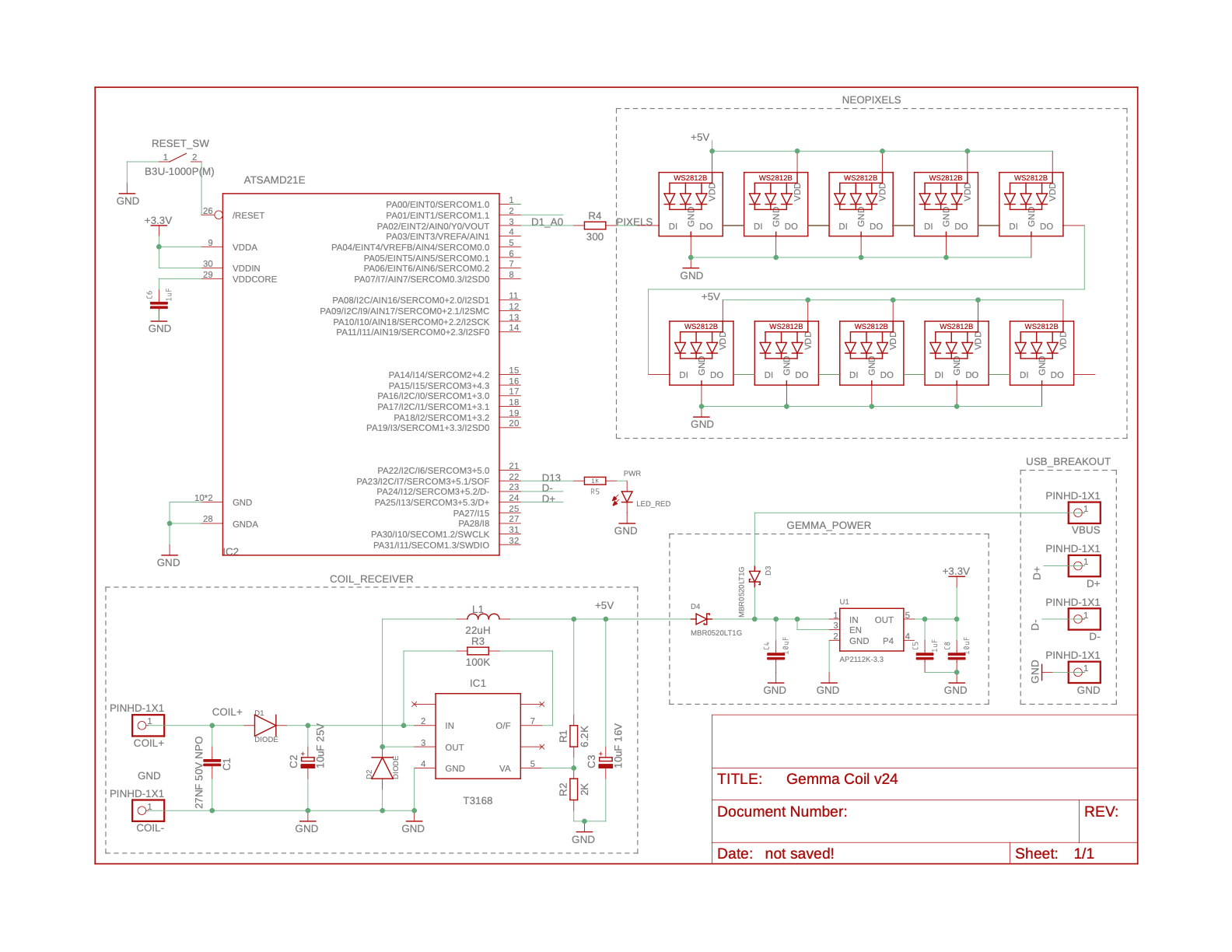
I’ve removed the battery connection and replaced it with a coil connection, removed a multicolor LED on the Gemma and replaced it with a string of LEDs, and removed the USB Mini B jack and replaced it with single pin breakouts.
Does this look generally reasonable? Do I have extraneous capacitors?