Is there interest in a 3D Modeling SIG or Office Hours or something where we get together and talk about the 3D Models we’re making and work through problems together?
I’m moderately experienced with Fusion, including the Manufacturing (CAM) features, and I know we have sculptors like @OctopusDream around.
I’m interested in learning more about how to deal with (mostly functional) meshes and modifying them. I’d also like to know more about how the use the non-solid workspaces in fusion. I’m not really aiming to be a 3d modeler, but I would like be less ham-fisted when tying to remix an STL
Heh. My usual reaction to having to remix an STL is to just re-model it. Every time I open Blender, I just nope out pretty quickly. Maybe some folks with more mesh editing experience would show up.
I used to do 3D modeling many moons ago but for 3D/digital uses. i’d like to know more about about specifics, limits and other details as it pertains to prints and how to scale up from prototypes.
I know a bit about Geometric Dimensioning and Tolerancing, and could find my way through a print with GD&T symbols on it with a cheat sheet (I’m sure I’ve forgotten some of the symbols). Is that the kind of thing you’re talking about? I’m sure @Kenneth is far better with that than I am. I think he’s doing a bunch of fixture design work for production machining.
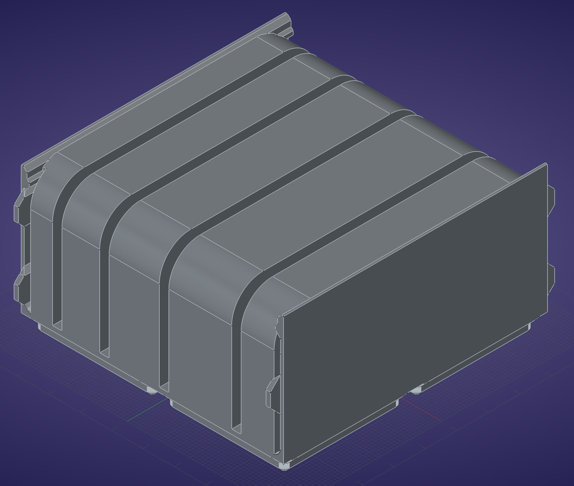
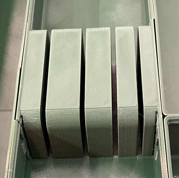
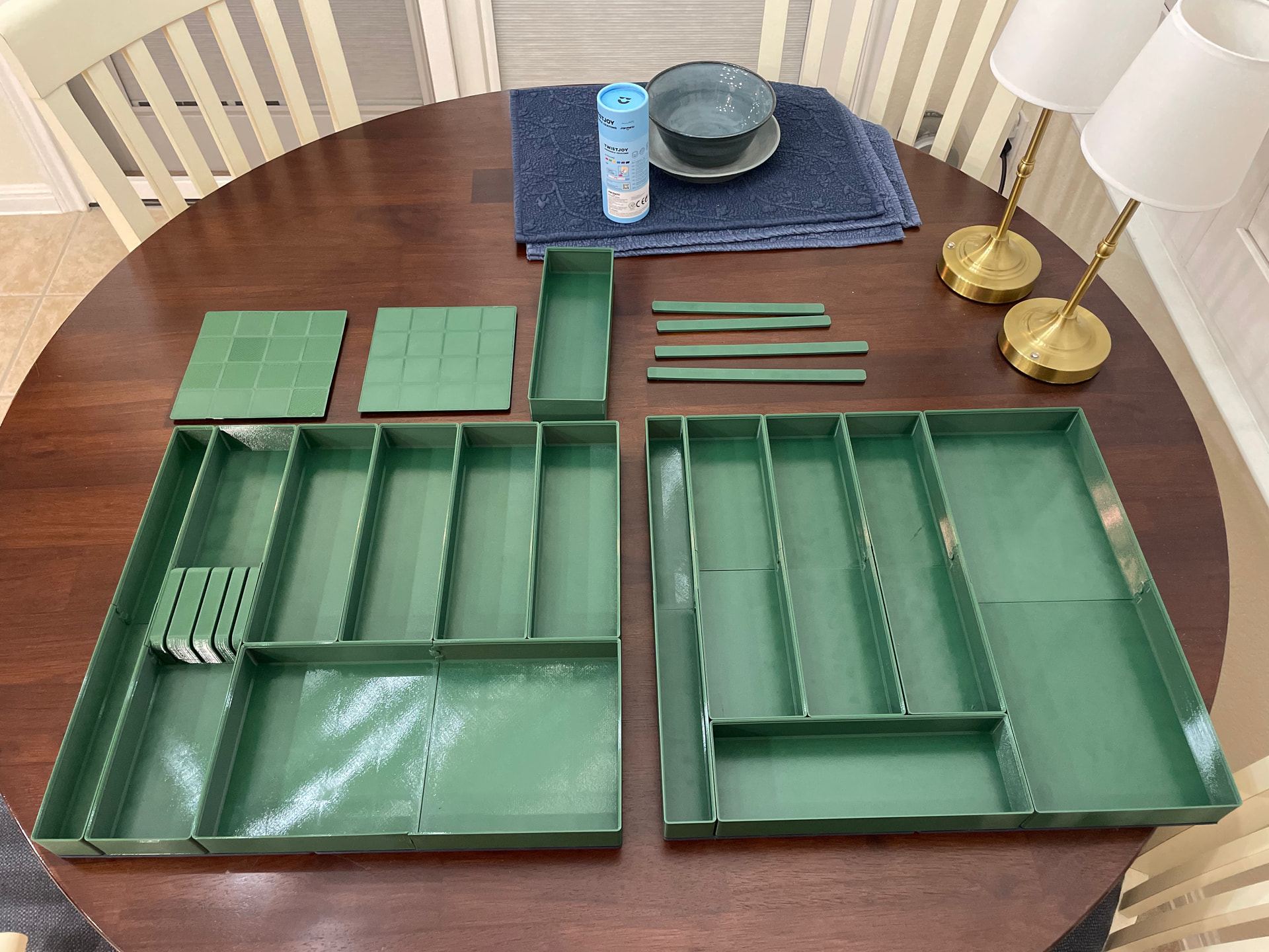
re: remix an STL… Just yesterday I had to bring in a Gridfinity 4x4 bin STL file, convert it to a solid, design a slotted knife holder solid, boolean them both together, export the combined STL, and print it. Sweet!
FreeCAD design of Gridfinity bin sidewalls combined with slotted knife holder as single solid
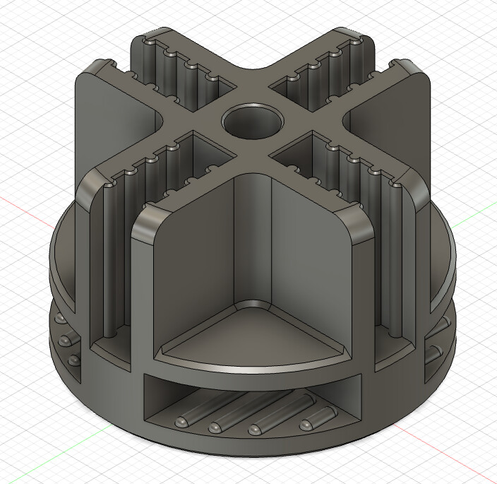
Nice. Don’t get me wrong, I do use existing STLs, but, for example, @MoonLitRose needed some connectors for her shelving. We found STLs of the basic thing, but I was sure we’d have to adjust tolerances to make them securely hold her particular shelving. The samples I printed on my Prusa Mini at home didn’t fit the same as the ones we printed on a P1S at Asmbly.
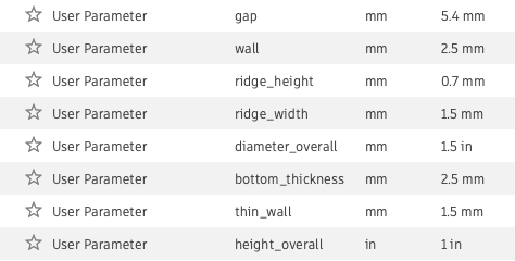
Re-modeling this from scratch allowed me to parameterize the critical dimensions and tweak them until I got a good fit. I’m sure there’s a way to do that on an existing STL by push/pulling faces or something, but this was the most straightforward way for me.
Unfortunately I don’t know of any “good way” to edit an existing STL. It’s baffling that the tech has gone as far as it has without adopting a better exchange format.
STL is a mesh of triangle surfaces. Curves and circles do not exist in this format, those curvy bumps were circular arcs in the original CAD tool, but that info is lost. A flat rectangular surface is at least 2 triangles but it could be a hundred. If you had to write software to edit an STL, there’s not an easy way to understand the intent of the design or the user input. To push or pull what an extrusion of a circular arc in the original CAD is now grabbing a single vertex or a single triangle out of dozens or hundreds that the arc feature turned into. So it doesn’t understand what you want to do. You don’t want to move just that vertex or push/pull just that one triangle face, and doesn’t understand the geometry of the original design.
What I’ve done in Fusion 360 (there’s other methods in other tools) is to import the mesh and try to convert it into Fusion 360 primitives. If all goes well, it could turn into flat surfaces and circular arc extrusions and the chamfer angles and fillet curves would be angles and curves. Now you have faces you can push/pull
But then has no design history or parameters. So if you want to widen or narrow the gap, you might need to select each of the 24 arc faces to push-pull and it will probably be unable to maintain the same chamfer size at the edge of the modified face because it doesn’t know it’s intended to be a constant width chamfer.
That’s if the mesh conversion is able to turn it into Fusion surfaces and very often it won’t. It’s taking in a mesh of hundreds or thousands of triangles and has to find the original intent out of that. It may not be accurate to the original, and often there’s entire surfaces missing and it can’t be converted into a solid, leaving you stuck.
A STEP file is a different matter. That isn’t limited to a mesh of triangles, the format directly represents exact flat surfaces, curves, and NURBs and can be edited. Much better. Still not the same as having a design history and parameters.
In most cases I would just start with a new design from scratch. I usually see a lot of things that could be done better, especially in manufacturability like avoiding overhangs.
Right. Sorry, I thought it was implicit in the “push/pulling faces” that you’d need to convert the mesh to faces, but it’s good to clarify the whole process.
I’m totally interested in getting together and talking all things 3D modelling!
My very first DCC software was Blender. Blender 2.6 to be exact That kickstarted my eventual career as a Character Artist in Game Dev.
Aside from sculpting and poly modeling software, I’ve picked up Fusion360 and Onshape for 3d Printing. If anyone is exploring CAD software options, I recommend checking out Onshape, the free plan is solid and it’s browser based!
edit: Unfortunately cannot make the first SIG meetup I’ll be out that weekend


 That kickstarted my eventual career as a Character Artist in Game Dev.
 I’ll be out that weekend