Roughing: 0.25" Flat … 8-Bit Video
Finishing: 0.125" Ball … SD Video
It starts with downloading an STL from TouchTerrain.
Roughing: 0.25" Flat … 8-Bit Video
Finishing: 0.125" Ball … SD Video
It starts with downloading an STL from TouchTerrain.
Neat. I’m curious about the vertical scale… It looks like it might be deep enough that you would need multiple clearing passes and also account for making sure deeper passes never caused spindle collision on the peak areas?
You can request an automated generation of any region as an STL/depth map via USGS’s public domain server. Including planets!
I did the a ton of these, including the entire Moon on the prior CNC, but the Lagunas are nowhere near as fast as that. In most cases you will want to scale up the Z several times out of proportion with the X and Y to make it more recognizable.
I actually found roughing passes were a waste of time and the bit-swapping is a potential source of screwups. A ball-end taper of the correct ball size for the job’s specific detail and scale, and enough length to cover the carving’s depth, does a great job.
There is little return on going below 15% stepover.
Give it a little extra Z below the surface, like 0.1", because it does often look, carve, and finish differently. Especially MDF which actually has densified faces, they take paint very differently near the surface.
Accurate mental imaginings, James! 
The software I used was Carbide Create Pro which nicely supports 3D carving. You can import STLs or depth map images and then make adjustments. One really useful tweak for topologies is Height adjustment. I simply played with Height till the mountain profile approximated what I saw in pictures.
As for the potential collisions, again, good anticipation! For the roughing pass I did actually use a 3” long down cut 0.25” flat end mill. No clearance issues. For the finishing pass I had to use the 0.125” ball nose and collisions could have been an issue. To avoid the possibility I tested different amounts of shank in the collet. When satisfied, I clamped … and there wasn’t more than half an inch being clamped. However, the step over was only 10% and very little material was removed during each pass so I wasn’t concerned.
I agree, topos can look great when there’s drama in the Z axis. 
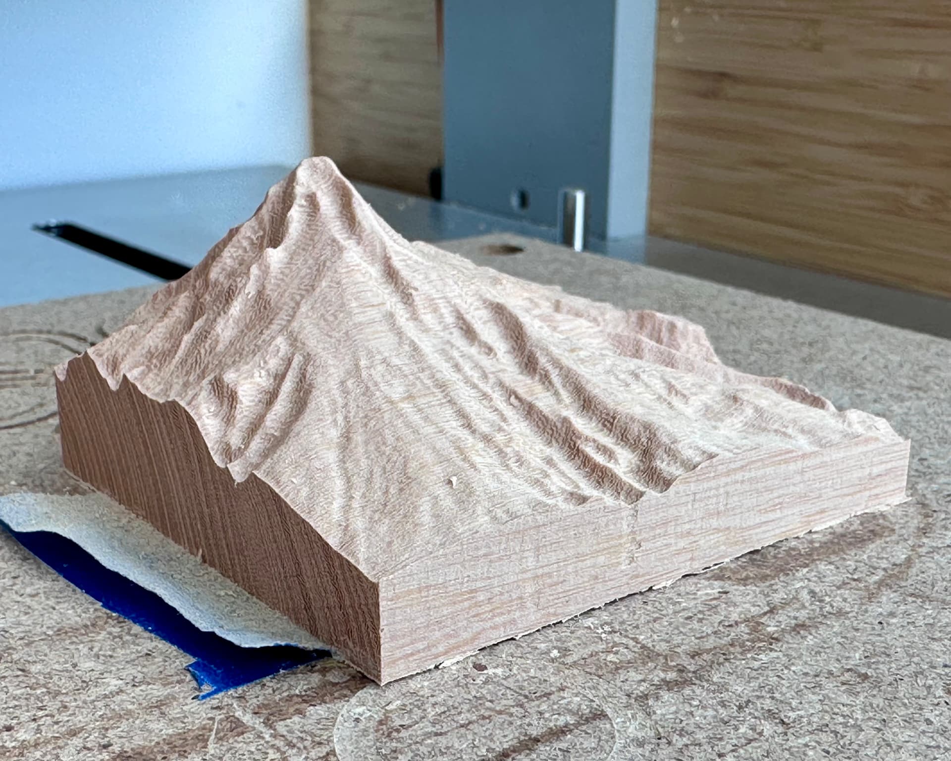
Out of curiosity I did a third pass with a 1/32” ball nose and a 50% step over. It may have been the resolution of the model being insufficiently detailed but I found no real benefit in this second finishing pass. Check it out; very little improvement.
That won’t help- in fact it can degrade the final finish somewhat.
The one and only ball diameter you should use on a non-rest-machining plan is the one that renders the smallest detail, but no smaller. You will want to verify this with V-Carve’s sim, but you MUST use the V-carve cheat code to enable its secret Ludicrous mode or the results will be deceptive. But you will also need a beefy computer to do this.
Or throw down a gamble on V-carve’s rest machining feature. Results not guaranteed, but it does bypass that guideline. There’s a major planning complication here though- you can’t know how much time it will take so you can’t compare the costs of different strategies. V-carve can’t know what the Lagunas will do, it has a trajectory planner with tech from the 90’s. It will take about 100 hrs realtime testing to work that part out.
Note that the real magnitude for the finest detail depends directly on the scale you are using on the final project. This creates a curious situation where, when the rules are followed, running your project larger doesn’t take that much longer than running it on a smaller scale.
Also, by “ball nose”, is this not a taper ball? Carving should always be done via taper ball, not ball nose, when the ball is below 1/8". Esp in hardwood.
50% stepover is a low quality finish which will show an unacceptable amount of scalloping, and may also overstress the bit. Always keep stepover in the 15%-30% range, and sequential ball passes should always be in rest mode.
How is the raster oriented? With the grain or against? It looks like it went with the grain, that doesn’t yield quite as good a result in most cases.
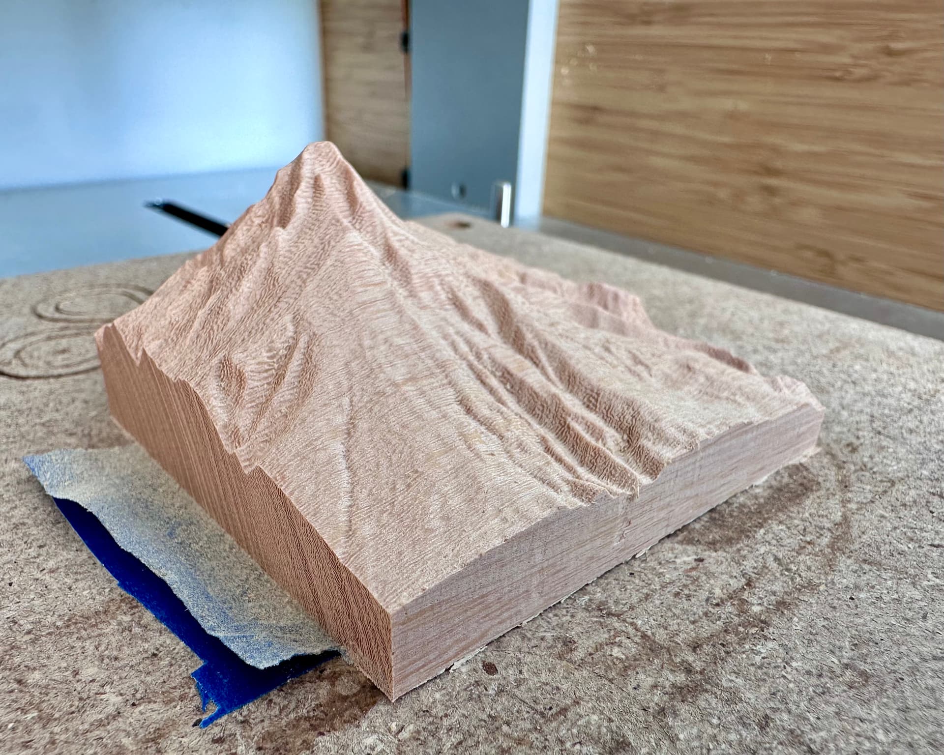
Gorgeous!! How thick was your starting material?
Can I use your photo as an example in the upcoming topo class? I think it’s a good example of how much map to select when downloading your data to get this really cool dramatic size.
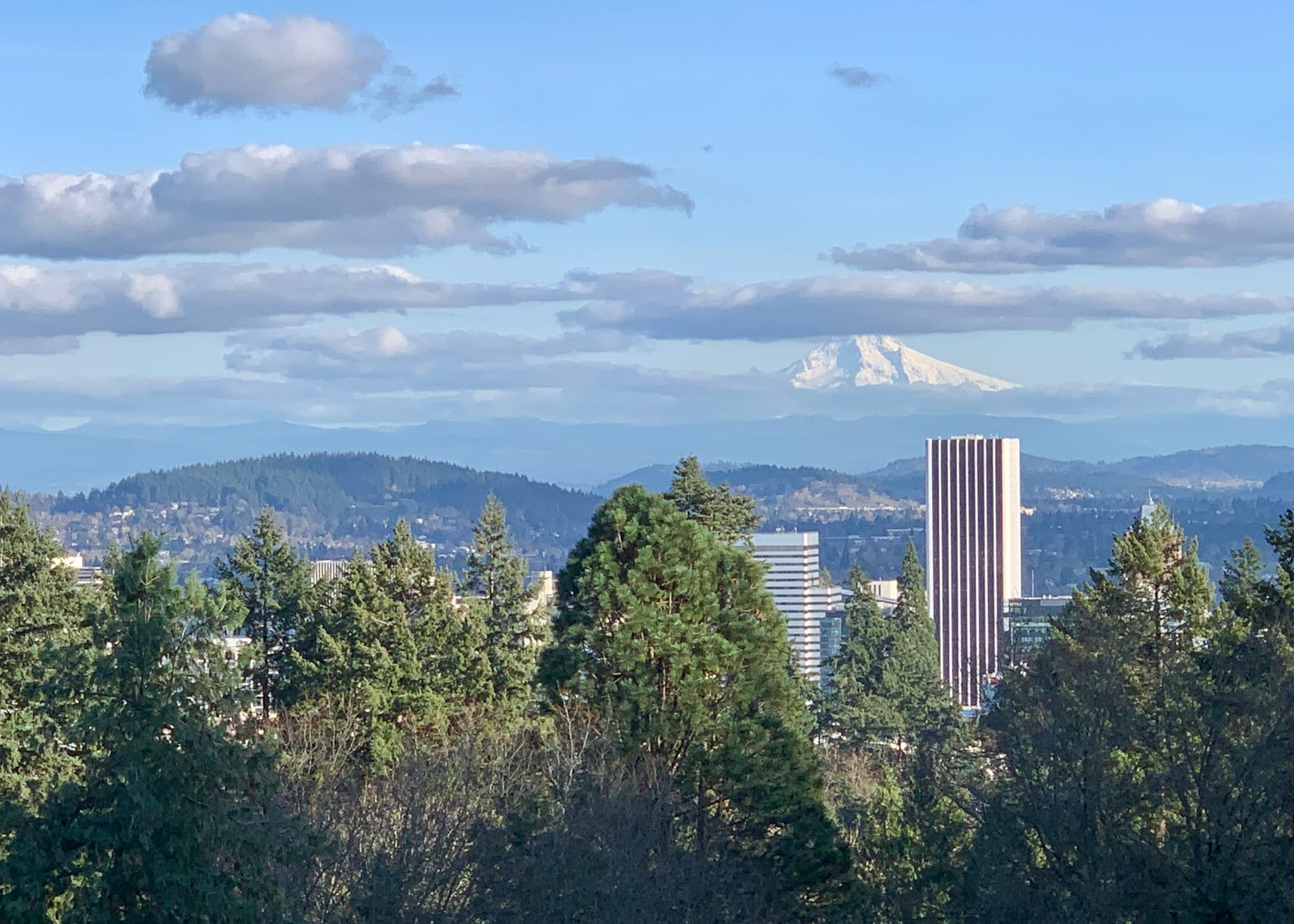
This is Mt Hood in Oregon right?
Of course you can use the image.
Let me know if the item itself would be useful.
Thank you SO MUCH for teaching topographic milling.
As for size, the stock is 2.75” x 2.75” x 1.375” and was a simple tribute to the city of my birth. On a clear day, from downtown Portland, Mt. Hood looms large. Yes, Oregon. Below is a picture I took last years.
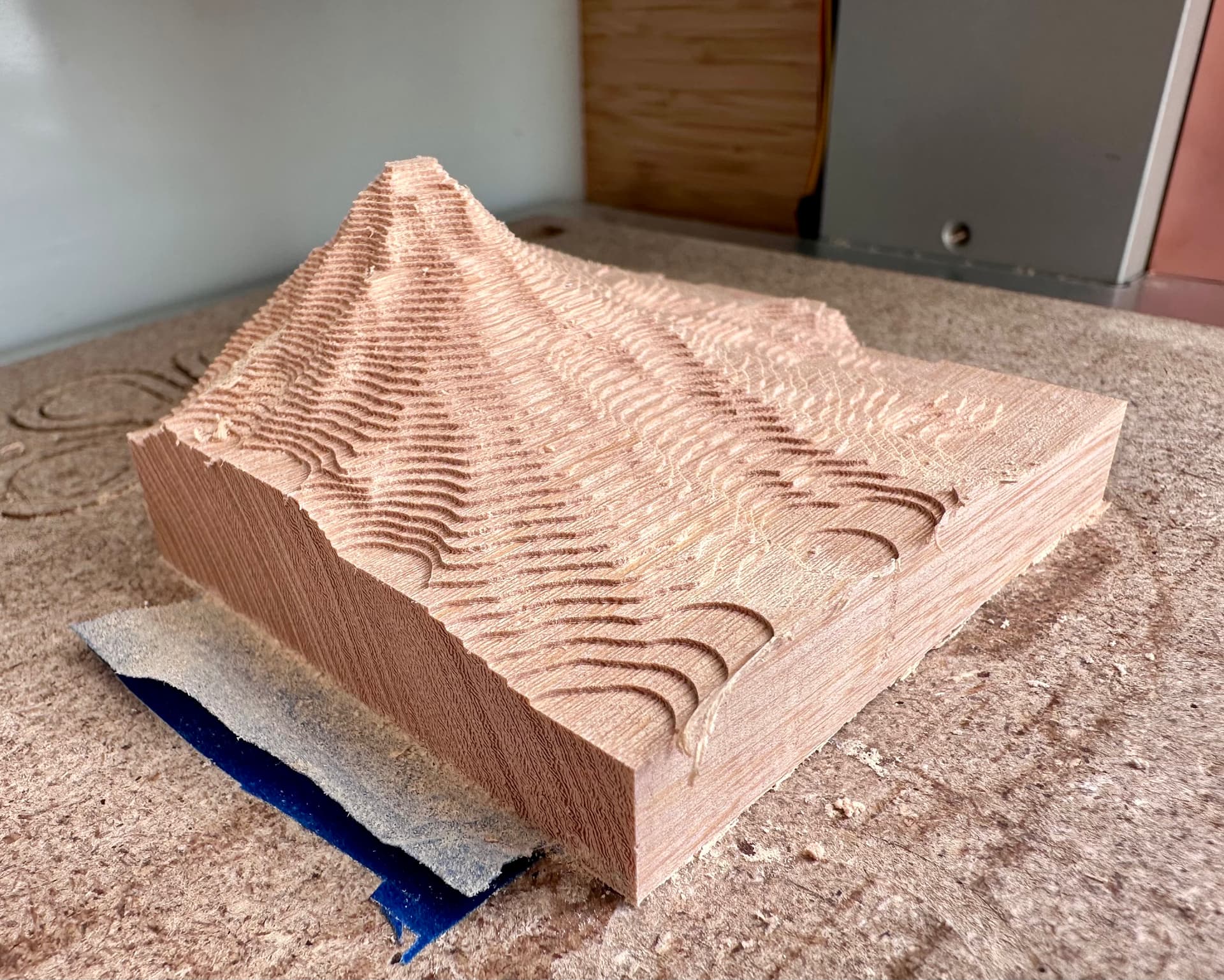
I respect what you know Danny so I performed another cut.
What’s different this time:
The stock is a different piece of the same wood and I can’t say the results are much different. A close inspection shows a nicer finish but that’s due to the two finishing passes at perpendicular angles. The tapered 1/32" ball mill is hardier which gives confidence. Even though finishing passes are non-demanding, a 1/32" ball nose on an 1/8" shank is pretty feeble.
Bottom line, the tapered mill didn’t seem to make noticeable difference.
I appreciate your dedication to science this and find the truth @TravisGood! Also, nice backdrop
Oops, it’s normally there but was temporarily out-of-frame when the double-sided tape failed. ![]()