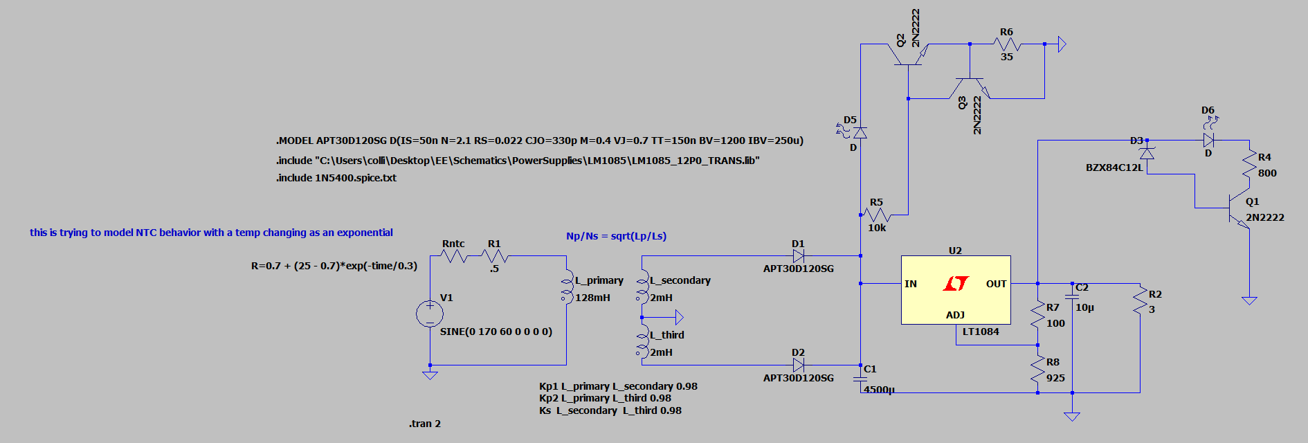
Howdy everyone. I am posting a schematic I made for a 12V single ended power supply. Topology revolves around a full wave rectifier that feeds a linear regulator (LT1084) and has the following features:
NTC resistor acting as a slow start to avoid blowing the planned 6A fuse (which is not in the LTspice schem). Fuse is rated so if we exceed 50% of the projected current on the mains side it trips.
2 indicator lights on the rectified output and 12V output. The one on the output of the rectifier uses a current sinking topology (Q2 & Q3) and should be pretty stable at all voltages. Idea was just to show that we have some semi-appropriate voltage coming out of the rectification stage. The 12V output stage uses a zener diode to establish a reference/bias voltage on the transistor Q1 - when we hit above 12V we get some current flow into the base of Q1 and then we pull current through the LED. Maybe there are better ways to do this, I don’t know.
No diode (flyback it may be called? don’t know if that is true in this case) is on the output as in some other schemes based on this quote from the datasheet - “The internal current paths on the LT1083 adjustment pin are limited by internal resistors. Therefore, even with capacitors on the adjustment pin, no protection diode is needed to ensure device safety under short-circuit conditions.”
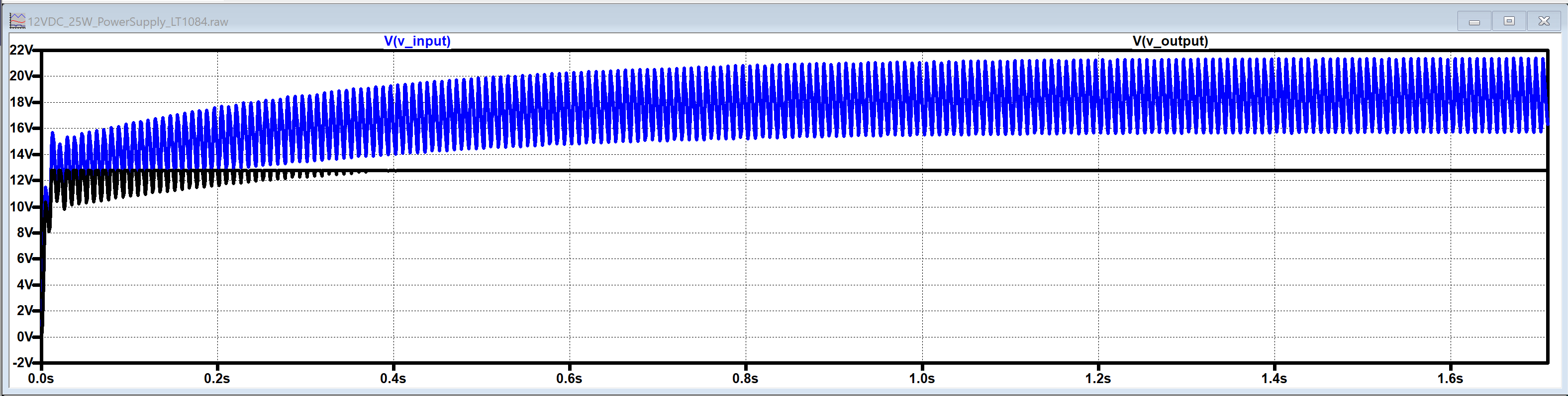
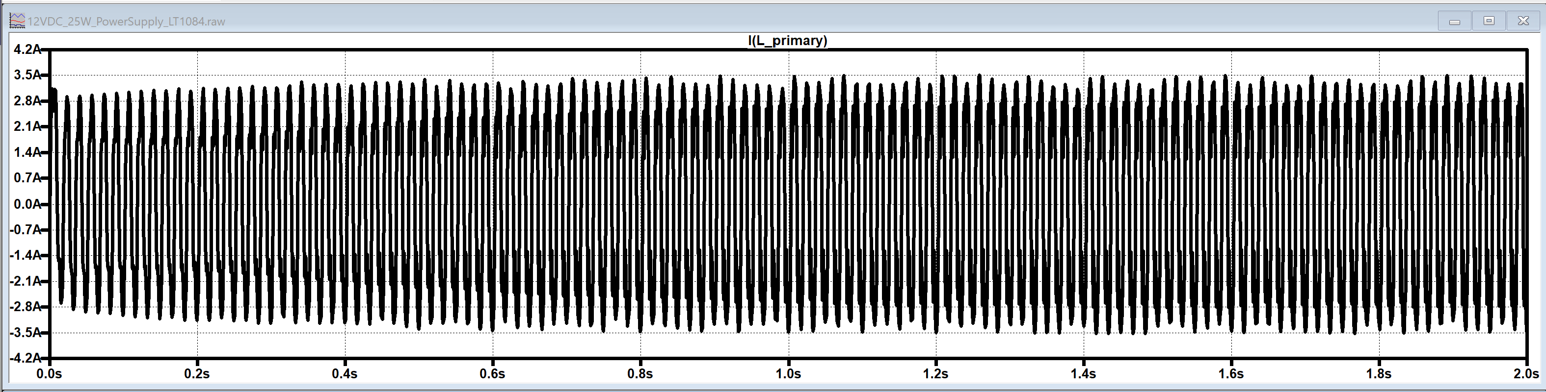
Plan is to convert from mains using a120V to 30V Center-Tapped Transformer (15V-0-15V). N = sqrt(Lprimary/Lsecondary) = sqrt(128/2) = 8. Therefore my peak voltage should be 170Vpp/8 = 21.25Vpp. This makes my Vrms = 21.25/sqrt(2) = 15V rms.
Now, here is where things get a little murky: After rectifying, I am expecting a ripple voltage of around 8.3V. I only see about 5V of ripple on the output in the sims. From some cursory research there is something called a conduction angle, and that may be influencing this. I don’t know if that matters or not. This last statement has unfortunately been said too much over the process of designing, hence the post. This is my first foray into power electronics so there could be a lot I am missing.
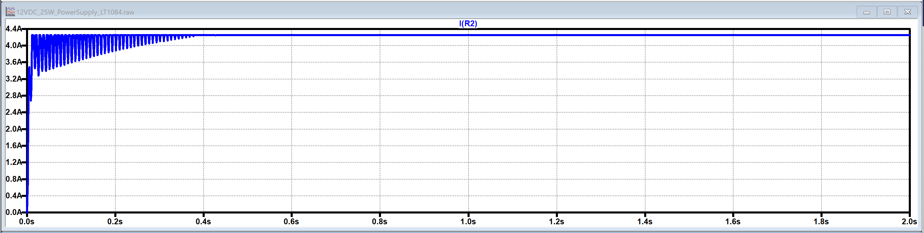
Model uses a 3ohm load to simulate a max draw of about 4.5A. I would be using this to feed two audio amplifiers that run at 12V 2A apiece.
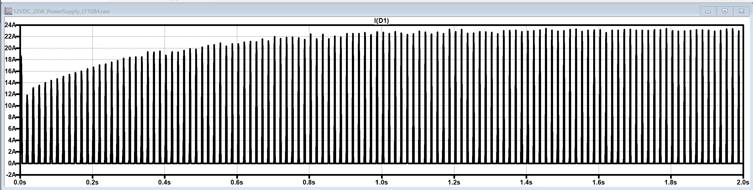
I picked the APT30D120SG arbitrarily since it is rated for 30A and had a spice model, and through hole packages.
That is most of the consideration I have put in. If you think I have missed something, or am assuming I am considering something else important, please mention it. I probably have missed something.
Unfortunately we can’t upload a .asc so I have just attached a picture. DM me and we can figure out how to email the schem and all the associated component files if you would prefer. Screentshots attached.