[Tarkin] Cuts in thick acrylic cut at an angle

Not sure how best to describe the issue I saw cutting 3/4" acrylic today, so here’s a photo:


Rather than the cuts being perpendicular to the bed, the cuts are at an angle. I put these two pieces opposite each other to more clearly show the angle that happened.

Any ideas?

Is that in the X or Y, and in which direction as is gets deeper, + or -?

FWIW, I saw something similar with 12 mm baltic birch yesterday. Unfortunately, I ran out of time to diagnose whether it was due to an alignment issue with the bed or gantry head, or possibly just uneven cutting along the Z axis. I was using 7mm focal distance (i.e. focused with the provided jig).

Oh, and @csader, I presume you also observed this on Tarkin? I will edit the post title with that assumption so other folks know which laser this applies to. If I’m wrong, please edit back.

1 Like

X and +

Ok so cutting front to rear, the beam slanted to the right as it went down?

What mm/sec and do you remember approx which part of the bed? Was it specific to one area or did you cover a lot of the bed?

Ok didn’t have material this thick before. Found your scrap

Reshimmed and now these are the same cut run twice, held flat on the bed each time, 180 rotation of the acrylic (not the job) after the first cut. This looks parallel now so I think we’ve got it dead nuts

1 Like

I don’t know what any of this means :rofl:

I’m assuming @dannym meant to post a pic

What does “re-shimmed” mean?

There is no particular adjustment for tramming in the X, so I cut up a strip from an aluminum can, folded it a precision number of times, shimmed it under the head’s left mounting screw, then realigned the #3 mirror and gave it a try.

When the stock is held flat and physically rotated 180deg, no external reference is needed. They will be parallel with no tram error. If there’s any error they will be diverging or converging depending on the directions of the tram error.

Hey, what settings did you use?

I think I had to go as slow as 4mm/s @ 100% to get it to cut all the way through.

Maybe I misunderstood the question here, but isn’t @dannym’s picture demonstrating the same thing as the first one @csader posted where the width of the cut changes with the depth (wider at the top, narrow at the bottom)? This behavior is something I think we probably expect with thicker material, but might also be a bit adjustable based on the focus depth you use (thinking back to previous lessons from Danny about the beam focus depth effects).

@valerie we’re actually not looking at the kerf shape, rather, the head had a small tram error that was evident in very thick acrylic and created a slant to the right, only evident on cuts going along Y axis. When viewed from the edge the cuts aren’t square but a parallelogram

Viewed from the top, there is no error. This is not a timing prob on the Y axis. It cuts at a slant to the left, down the Z, because the head is slightly slanted where it mounts on the gantry carriage. Instead of pointing straight down the head was a few degrees to the left, or counterclockwise if you were kneeling down and looking to the back of the bed

The tram error was adjusted by physically remounting the head. Fortunately this is a one-time setup issue and does not need to be repeated unless the axis is disassembled for some reason

4mm/sec sounds right
I was trying one vs two passes, and it did seem better, faster than single pass. Interesting.

Oh to clarify “these parallel cuts showing the results of shimming out the tram error” means I adjusted it and it should cut very straight now.

Test explained:

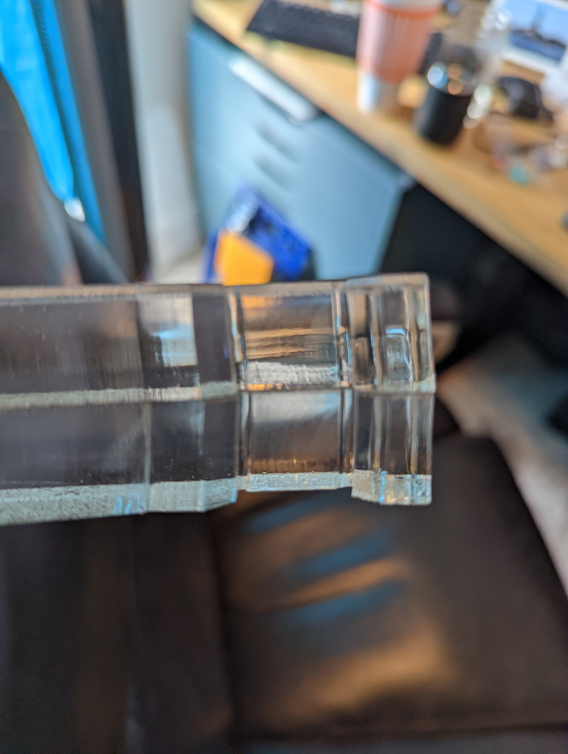
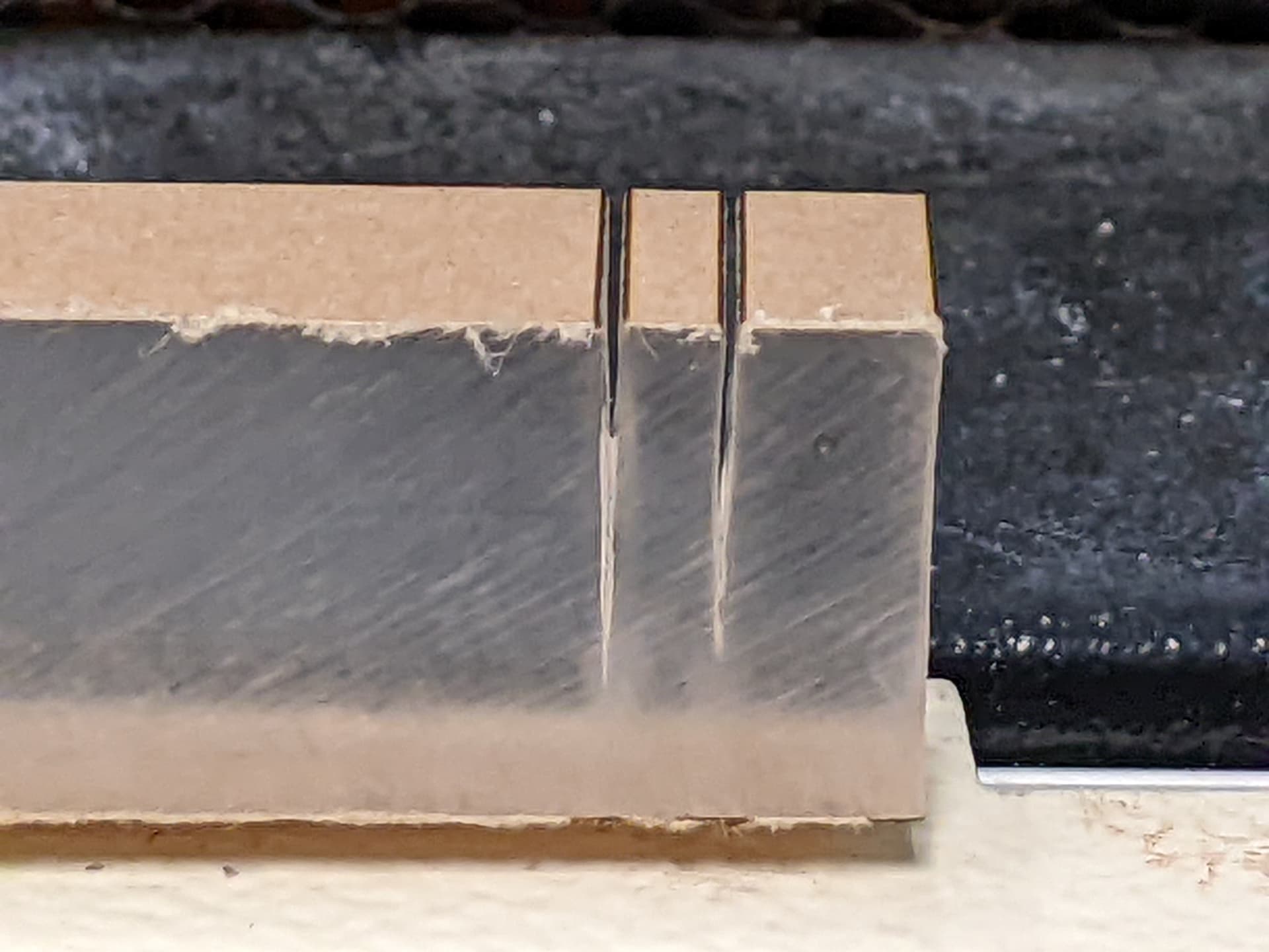
The problem is the head is not mounted perfectly and the beam is not coming down normal to the plane of the bed. It will cut at a slight slant in one plane, in this case along the X. This is not readily apparent on thin materials, nor is it readily apparent on wood even if it’s of sufficient thickness due to wood being opaque and has a less regular surface due to variable contraction of the surface where it’s “cooked” near the edge. It is most apparent in thick clear acrylic.

The key to the test that the pic shows is that the work was physically rotated and the same cut taken again slightly to the side. This is proving a CORRECTED beam. Sorry, I didn’t show what it was before correction.

If we didn’t rotate the work, this means nothing as the lines would still be parallel whether or not the beam was a perfect 90 deg to the bed. The error would still be there as a slanted cut, but this slant is hard to see much less quantify and two lines with the same slant are of no additional value.

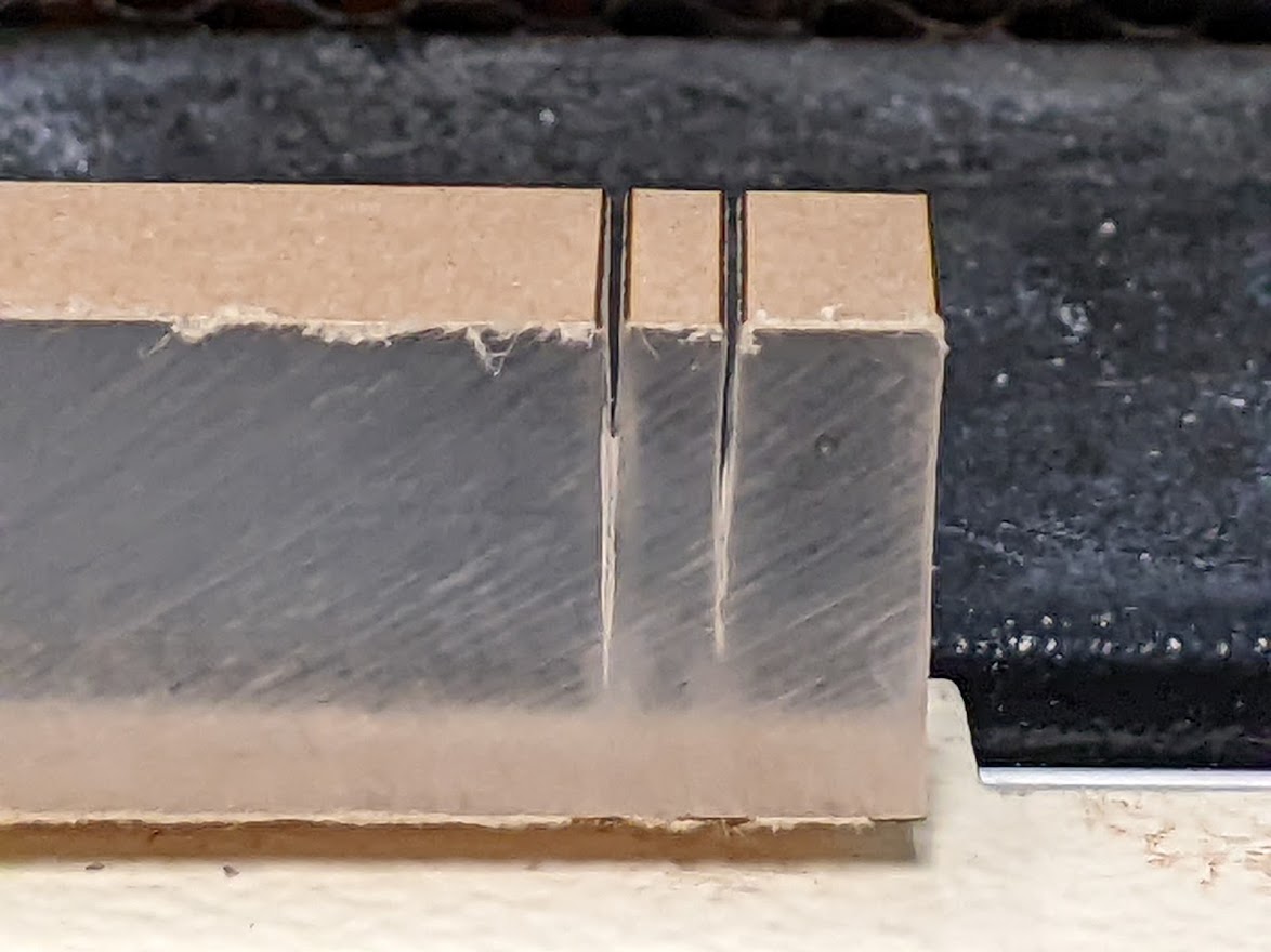
But by rotating the piece 180 deg before performing the second cut, that will reverse the direction of the first slant. Any error is readily apparent as the two lines will not be parallel, they will form a “V” or an inverted “V” depending on the direction of the slant. On close lines, small amounts of angle is very obvious.

Accuracy does depend on having the piece flat on the plane of the bed. The honeycomb needs to be flat (it is) and the test piece needs to be an inherently flat material and should be long enough to know what flat is when it’s held down, like 6" or more. It needs to be thick so the error shows up (3/4" is great), and it’s much more apparent in acrylic than wood.

So, armed with a way to accurately measure tram angle error, the carriage actually runs on top of the gantry rail and the head has a right angle bracket secured by just two vertical screws. So if we put in a shim under one screw, it will jack up that side and ultimately skew the angle the beam in that direction.

The “shim” is a strip cut from aluminum soda can folded over however many times is needed to get the proper thickness to prop up one side of that interface once tightened down and the corner folds crushed flat so only the net thickness is just the number of aluminum folds. In this case I think it was around 8 or 10. You start with a few folds but leave more of the strip hanging off to add more folds in if it needs more thickness. Iterate, take notes of how many folds are too few and what’s too many, using the parallel cuts in 180-rotated material test each time,

After each shim placement, it is necessary to realign the #3 mirror (the one on the laser head) to ensure the cutting beam is perfectly centered where it exits through the nozzle’s orifice. The nozzle gets better high-speed focused air flow when it’s as small as possible, so the clearance is tight and any repositioning of the head such as shimming can shift that beam to where it will clip on the cone. This reduces net cutting power and the cone will get very hot after a minute of full-power cutting later (a good test to perform).

That’s a separate story on how to adjust the #3.

@dannym just FYI I came in and did the exact same job and got the exact same result as before. I tried doing some test cuts like yours above beforehand and they looked ok, so not sure what happened when I did the actual cutting.

A picture would help. The head hasn’t been moved since I did the calibration on it so it should still be dead nuts- but you said it passed the test cuts anyways so I wouldn’t suspect the machine’s tramming.

How thick is your material? In thick material (I’d say >1/2") there is often some “meandering” of the cut. The kerf width remains the same but it can wander slightly. Which is hard to explain why, but that’s possible with any laser.

I’ve ordered a different head to try BTW. This is pretty simple to switch out, the carriage stays on the gantry they just screw onto the carriage and we make new focus tools. There’s always been some clipping of the beam on the cone even with the best centering, but I think I can get a bit more. Different issue, though.