I want to cut some files that will have 3D profiles and it seems like it would be challenging to setup in Vcarve. If I’m using another CAM program (e.g. Solidworks CAM), would I just export to raw g code and import that directly into Axis?
Is there anything else I should know? Does the file export need to have certain settings correct to import to the Axis software?
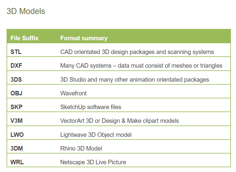
Vcarve uses the 3D file imports listed in the chart below. The basic workflow is to use the following toolpaths: 3D Roughing and 3D Finishing. You’ll see screens and forms in the flow that won’t look familiar but don’t be too concerned. Noodling through them isn’t too tough. When I teach 3D I have students perform the Magnolia cut, which is detailed in this video. Good luck!
Make sure to number your tools in increasing order from 1. Don’t start on T3 for example. Also be careful with the tool length compensation codes like G43. You’ll need to check the tooltable in Axis and make sure all the tool offsets are all 0. It’s unlikely that someone has changed them but make sure just in case. Don’t use any tool compensation codes in your Gcode if you can disable them.
It’s a limited 3D import option to preserve the market positioning for Aspire. The basic constraint is one non-Vectric file import unless they’re Vectric-sold V3M files. For instance, you can import one STL file for 3D carving which isn’t as much a constraint as you might think if you do your model building in a different package. However, you can import all the Design & Make 3D files you want.
I use Solidworks CAM & the large CNC. If you can’t get it sorted, let me know. Here’s a list of things that I try to remember:
I’ve found the Z to be a little bit unstable, a little variation over the length of the table. Some fixes were made to the machine that should fix it, but I haven’t verified it yet. It depends on your part how critical this is. If Z over a large area is critical, check the grooves in the table to see if they are mostly equal-depth across the table. X&Y are accurate to greater than 0.2mm across the table, and that was just as good as I could tell with my testing. I haven’t checked the accuracy of rack-adjustment lately. I plan on doing that in a few weeks. This will only matter on huge 4x8 pieces that need tight mechanical fits across the length.
The Post-processor I used for linux CNC… I had to disable the function generation feature. I think LinuxCNC was upgraded recently, so maybe iit’ll like functions more? Not sure about that. I’d suggest disabling use of functions.
In Soildworks CAM, I had to disable G43/tool offset, but leave cutter comp on. This forces SWCAM to generate toolpaths that take into account the tool width.
Solidworks CAM internally makes use of tool switching. You need to ensure all tools are set to 0/0/0/0 offset. You can go to the file menu, and there’s something to view the tool table. View it, and it should be all blank. If there’s numbers in there, it will cause problems. You need to check this every time you step up to the machine. Every now and then somehow it gets set somewhere, and if I don’t catch it, it ruins my piece.
I have to down-rate the speed that SWCAM picks for the machine. I have to drop both the feed and speed to 40% of the generated value. But that may partially be because I’m cutting metal, or solidworks wants a higher speed. Or both.
I select a light-duty machine, with an 18k spindle speed.
Sure, I’ll be happy to help. Just if I wasn’t clear, sometimes solidworks generates g-code that linuxCNC doesn’t like, but the only way to know if linuxCNC likes it is to try it to actually try and load it in linuxCNC.